Devices and methods for effectuating percutaneous Glenn and Fontan procedures

a technology of percutaneous glenn and fontan, applied in the field of transcatheter devices and methods, can solve the problem of unmet need for a purpose-built cavopulmonary anastomosis device, and achieve the effect of enhancing apposition

Active Publication Date: 2019-10-01
UNITED STATES OF AMERICA +1
View PDF154 Cites 1 Cited by
  • Summary
  • Abstract
  • Description
  • Claims
  • Application Information

AI Technical Summary

Benefits of technology

[0005]A transcatheter approach for obtaining the results of the surgical procedures described above can revolutionize the management of these children with congenital heart disease. As an alternative to the Norwood Procedure, Bi-directional Glenn operation and Fontan procedure, a nonsurgical transcatheter intervention can limit the burden of surgery for infants while also reducing cost. There is a considerable unmet need for a purpose-built cavopulmonary anastomosis device. To Applicant's knowledge no commercial alternatives exist for off-label medical use.
[0006]To achieve these and other advantages and in accordance with the purpose of the disclosure, as embodied herein, in one aspect, the disclosure includes embodiments of a cavopulmonary self-expanding implant to permit an interventional cardiologist to create a shunt between the Superior Vena Cava (SVC) and the main pulmonary artery (MPA). The implant can provide an urgently needed option for children with congenital heart failure to avoid the burden of a three-stage surgery (so called palliative surgery), the burden of an additional heart transplantation after failure of the palliative surgeries, or of the lifelong medication intake after direct heart transplantation.
[0007]In some implementations, a radially self-expanding endograft prosthesis is provided that includes (i) distal flange that is self-expanding and configured to flip generally perpendicularly with respect to a body of the prosthesis to help seat the prosthesis against a tissue wall, (ii) a distal segment extending proximally from the distal flange that has sufficient stiffness to maintain a puncture open that is formed through a vessel wall (iii) a compliant middle segment extending proximally from the distal segment, the middle segment being more compliant than the distal segment, and having independently movable undulating strut rings attached to a tubular fabric, the combined structure providing flexibility and compliance to allow for full patency while flexed, the segment being configured to accommodate up to a 90 degree bend, (iv) a proximal segment having a plurality of adjacent undulating strut rings that are connected to each other, the proximal segment being sufficiently stiff to seat within and urge against a vessel wall, and (v) a proximal end including a plurality of openings around the proximal end for accommodating a tether that is threaded through the openings to cause the prosthesis to collapse radially inwardly when tension is applied to the tether.
[0009]The prosthesis can further include a flared or bell-shaped proximal region to enhance apposition against the interior wall of a lumen. The prosthesis can further define at least one fenestration through a sidewall thereof to permit leakage of bodily fluid through the fenestration.
[0010]In some implementations, a tubular prosthesis is provided having a first flanged end and a second flanged end, each flanged end being configured to urge against an inner surface of a first body lumen and a second body lumen when the prosthesis is mounted through openings formed into the walls of the first body lumen and second body lumen. The prosthesis can be adjusted in length. The prosthesis can include proximal and distal portions connected by a central elastic region such that the prosthesis can be stretched to cause the flanged ends of the prosthesis to pull against the lumens that the flanged ends are mounted into.

Problems solved by technology

There is a considerable unmet need for a purpose-built cavopulmonary anastomosis device.

Method used


Image

  • Devices and methods for effectuating percutaneous Glenn and Fontan procedures
  • Devices and methods for effectuating percutaneous Glenn and Fontan procedures
  • Devices and methods for effectuating percutaneous Glenn and Fontan procedures

Examples


Embodiment Construction

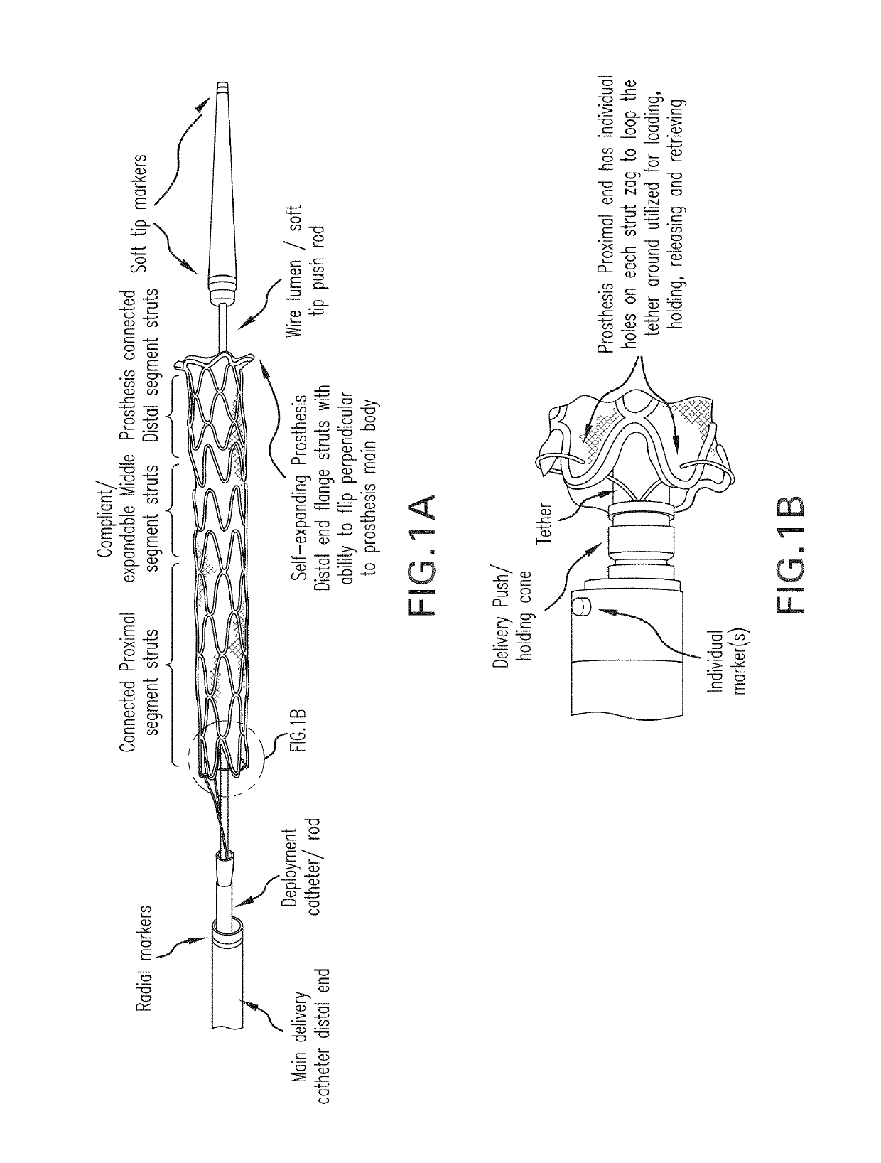
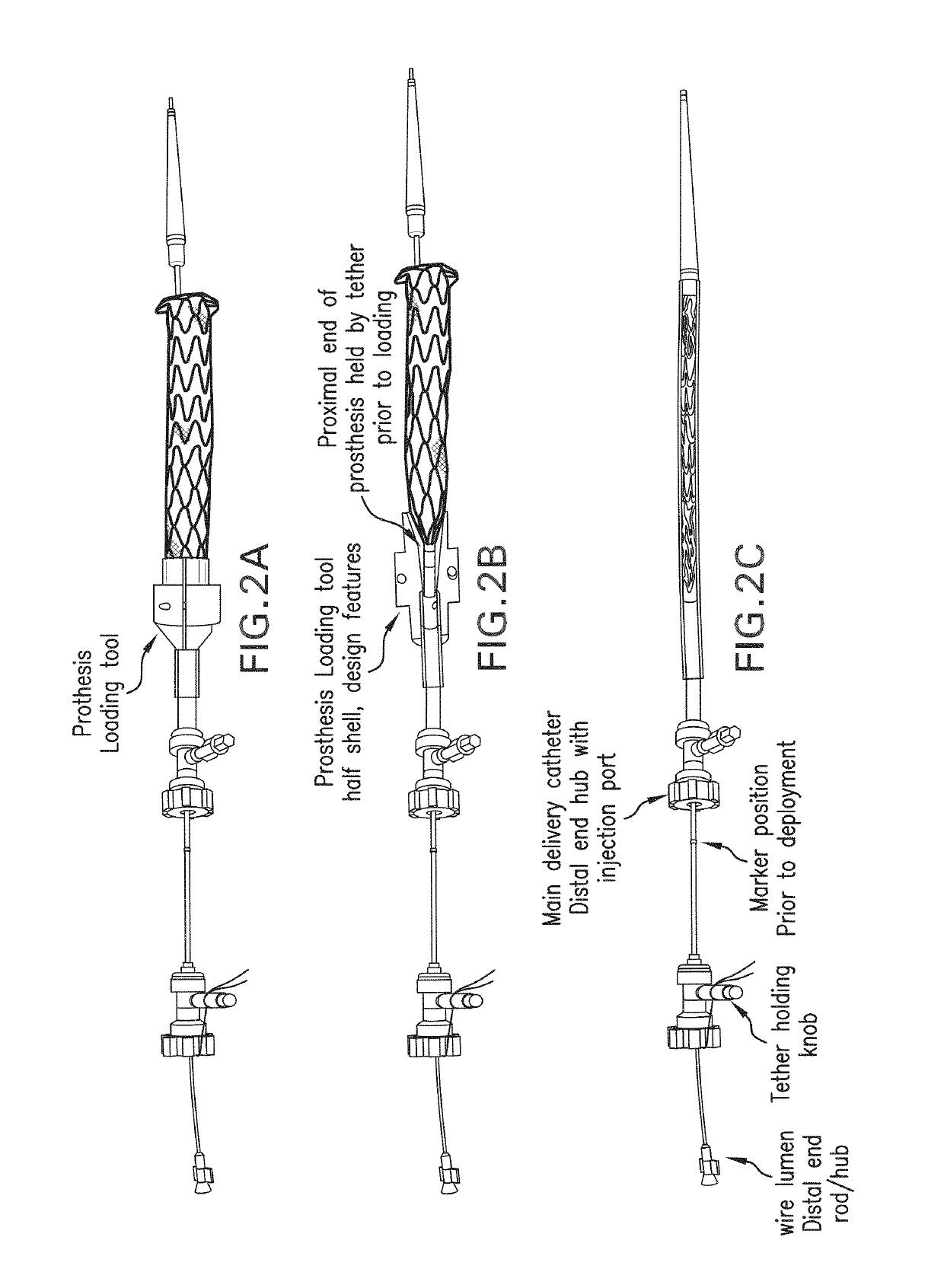
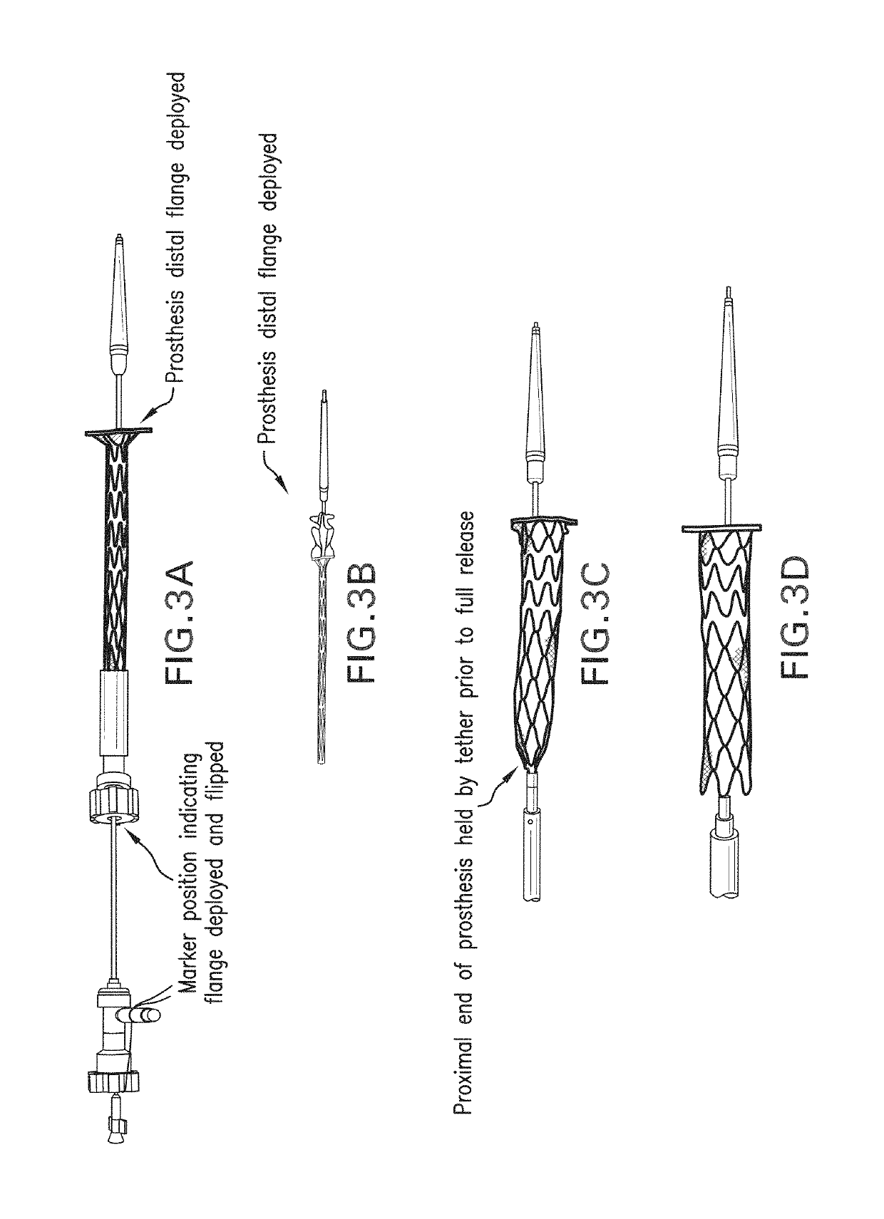
[0033]Reference will now be made in detail to the present preferred embodiments of the disclosure, examples of which are illustrated in the accompanying drawings. The method and corresponding steps of the disclosed embodiments will be described in conjunction with the detailed description of the system. The exemplary embodiments illustrated herein can be used to perform Glenn and Fontan procedures, but percutaneously. It will be appreciated, however, that the disclosed embodiments, or variations thereof, can be used for a multitude of procedures involving the connection of blood vessels or other biological lumens to native or artificial structures.

[0034]Embodiments of a disclosed TCBE (Transcatheter Cavopulmonary Bypass Endograft) represent a potential breakthrough for physicians and young patients who require a safe, less-burdensome, and effective alternative to open heart surgery: a percutaneous approach to heal congenital heart failure.

[0035]In particular implementations, the und...


PUM


Abstract

In some implementations, a radially self-expanding endograft prosthesis is provided that includes (i) distal flange that is self-expanding and configured to flip generally perpendicularly with respect to a body of the prosthesis to help seat the prosthesis against a tissue wall, (ii) a distal segment extending proximally from the distal flange that has sufficient stiffness to maintain a puncture open that is formed through a vessel wall (iii) a compliant middle segment extending proximally from the distal segment, the middle segment being more compliant than the distal segment, and having independently movable undulating strut rings attached to a tubular fabric, the combined structure providing flexibility and compliance to allow for full patency while flexed, the segment being configured to accommodate up to a 90 degree bend, (iv) a proximal segment having a plurality of adjacent undulating strut rings that are connected to each other.

Description

CROSS-REFERENCE TO RELATED APPLICATIONS[0001]The present patent application claims the benefit of priority to U.S. Provisional Patent Application Ser. No. 62 / 219,118, filed Sep. 15, 2015, and U.S. Provisional Patent Application Ser. No. 62 / 363,716, filed Jul. 18, 2016. Each of the foregoing patent applications is incorporated by reference herein for any purpose whatsoever.FIELD OF THE DISCLOSURE[0002]The present disclosure relates to devices and methods for transcatheter (i.e., performed through the lumen of a catheter) Glenn shunt and Fontan systems (transcatheter cavopulmonary bypass endograft prosthesis and delivery) for nonsurgical, percutaneous extra-anatomic bypass between two adjacent vessels.BACKGROUND[0003]Children born with single ventricle physiology (SVP), a form of cyanotic congenital heart disease (CCHD), represent 7.7% of all congenital heart disease patients and have a birth incidence of approximately 4-8 per 10,000. In the United States, this represents approximatel...

Claims


Application Information

Patent Timeline
Patent Type & Authority Patents(United States)
IPC IPC(8): A61F2/06A61M25/00A61B17/11A61F2/82A61F2/915A61B17/00A61F2/07
CPCA61B17/11A61M25/00A61F2/07A61F2250/0082A61F2250/0098A61B2017/1139A61B2017/1107A61F2002/91575A61F2002/828A61B2017/00252A61F2/064A61F2250/0029A61F2250/0039
Inventor RAFIEE, NASSERMACDONALD, STUARTLEDERMAN, ROBERT J.RATNAYAKA, KANISHKAMACDONALD, BIWEIRAFIEE, ALANA
Owner UNITED STATES OF AMERICA
Why Eureka
Try Eureka