Control device for supercharging system
a control device and supercharging technology, applied in the direction of electric control, machines/engines, combustion engines, etc., can solve problems such as the breakage of various devices, and achieve the effects of suppressing the rapid fluctuation of the boost pressure, preventing the occurrence of surging in advance, and controlling the boost pressure quickly
- Summary
- Abstract
- Description
- Claims
- Application Information
AI Technical Summary
Benefits of technology
Problems solved by technology
Method used
Image
Examples
first embodiment
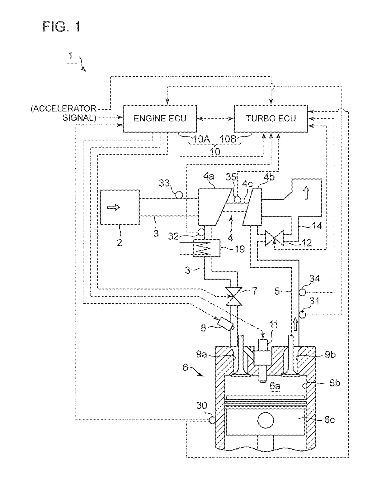
[0068]FIG. 1 is an overall configuration diagram of an engine system to which a control device of a supercharging system according to the first embodiment of the present invention is to be applied.
[0069]In the engine system 1 according to the present embodiment illustrated in FIG. 1, air (intake air) introduced into an intake duct 3 via an air cleaner 2 flows into a compressor 4a of a turbocharger 4 (supercharger). The turbocharger 4 includes a compressor 4a disposed in the intake duct 3, a turbine 4b disposed in an exhaust duct 5, and a rotor 4c coupling the compressor 4a and the turbine 4b. The turbine 4b is driven to rotate by exhaust energy of exhaust gas discharged from the engine 6, and thereby the compressor 4a is coaxially driven, so as to compress the intake air flowing into the compressor 4a.
[0070]The intake air compressed by the compressor 4a is cooled by an intercooler 19, and an intake amount of the intake air is adjusted by a throttle valve 7. The intake air is premix...
second embodiment
[0109]FIG. 11 is an overall configuration diagram of an engine system to which a control device of a supercharging system according to the second embodiment of the present invention is to be applied. The engine system 1a of the present embodiment is basically similar to the embodiment illustrated in FIG. 1 in terms of configuration, except that the engine system 1a does not include the bypass channel 14 and the waste-gate valve 12. Thus, the same component is associated with the same reference numeral and not described in detail.
[0110]In the present embodiment, as illustrated in FIG. 11, the turbocharger 4 is a variable turbocharger including the turbine 4b driven to rotate by exhaust energy of exhaust gas discharged from the engine 6, the compressor 4a driven coaxially with the turbine 4b, and a variable control mechanism 4d for controlling a flow of exhaust gas that flows into the turbine 4b. The variable control mechanism 4d is adjusted to control a flow of exhaust gas flowing in...
third embodiment
[0113]FIG. 12 is an overall configuration diagram of an engine system to which a control system of a supercharging system according to the third embodiment of the present invention is to be applied. The engine system 1b of the present embodiment is basically similar to the embodiment illustrated in FIG. 1 in terms of configuration, except for the two-stage turbo-charging system including two turbochargers, a high-pressure stage turbocharger 4A and a low-pressure stage turbocharger 4B. Thus, the same component is associated with the same reference numeral and not described in detail.
[0114]In the present embodiment, as illustrated in FIG. 12, the supercharger for compressing intake air to be supplied to the engine 6 includes the high-pressure stage turbocharger 4A and the low-pressure stage turbocharger 4B. The high-pressure stage turbocharger 4A includes a high-pressure stage turbine 4Ab disposed in the exhaust duct 5 of the engine 6 and driven to rotate by exhaust energy from the en...
PUM
 Abstract
Description
Claims
Application Information
 - R&D
- Intellectual Property
- Life Sciences
- Materials
- Tech Scout
- Unparalleled Data Quality
- Higher Quality Content
- 60% Fewer Hallucinations
Browse by: Latest US Patents, China's latest patents, Technical Efficacy Thesaurus, Application Domain, Technology Topic, Popular Technical Reports.
© 2025 PatSnap. All rights reserved.Legal|Privacy policy|Modern Slavery Act Transparency Statement|Sitemap|About US| Contact US: help@patsnap.com


