
Setup and method for noise parameter measurement

a noise parameter and measurement method technology, applied in the field of low-noise microwave and rf transistor chips, can solve the problem of more important limitation being availability

Active Publication Date: 2019-10-01
TSIRONIS CHRISTOS
View PDF8 Cites 2 Cited by
  • Summary
  • Abstract
  • Description
  • Claims
  • Application Information

AI Technical Summary

Benefits of technology

The invention is a way to measure the noise parameters of an RF device, like a transistor chip, while it is still on a semiconductor wafer. This is done by connecting the chip to two parallel sets of wafer probes or a set of differential probes. The method allows for accurate measurements without needing to move the probes, and can be programmed to measure different parameters or executed by hand. This invention is useful for improving the quality and efficiency of RF devices during manufacturing.

Problems solved by technology

An even more important limitation is availability.

Method used


Image

  • Setup and method for noise parameter measurement
  • Setup and method for noise parameter measurement
  • Setup and method for noise parameter measurement

Examples


Embodiment Construction

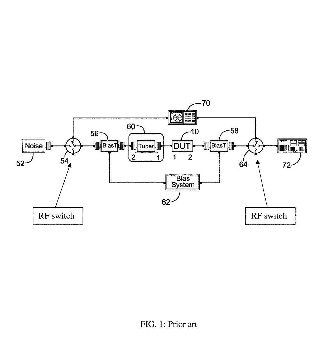
[0038]The test setup disclosed here (FIG. 6) can be used instead of all hitherto used traditional setups (FIGS. 1 and 5). It comprises a network analyzer (VNA) (602) connected to wafer probes using cables (600, 61), a control computer (68) which controls (67) the tuner (65), the VNA (602) and the receiver (601) using digital cables (69), a calibrated noise source (66) and bias networks (embedded in the wafer probes (612 and 614) or external, depending on the embodiment (see also FIGS. 8, 9 and 12). Because the noise parameters of a DUT cannot be measured directly, the noise figure (F.total) of the whole chain of “tuner (65)-DUT (63) and noise receiver (601)” is measured at a number of source impedances (604) and the noise parameters are extracted using linearization and statistical algorithms (see ref. 14). The noise figure of the DUT (F.dut) itself is extracted from F.total. The relation allowing this is described by the FRIIS formula (see ref. 2). F.dut=F.total−(F.rec−1) / Gav.dut {...


PUM


Abstract

A noise parameter test setup allows accurately measuring the four noise parameters (Fmin, Rn, ┌opt) of microwave transistors over a wide frequency range using two distinct wideband measurement paths, based on differential wafer probes, instead of SPDT switches, to commute between s-parameter (signal) measurement and noise measurement path, avoiding thus the uncertainty of the accuracy as well limited availability of SPDT switches. Calibration of the system is the same as when using switches, when hopping the DUT chip from one set or subset of probes to the next. Additional power control precautions of the VNA sources are necessary to avoid injecting signal power into the sensitive noise receiver during s-parameter measurements and jamming the weak noise power during noise measurement.

Description

PRIORITY CLAIM[0001]Non applicable.CROSS-REFERENCE TO RELATED ARTICLES[0002]1. H. ROTHE and W. DAHLKE, “Theory of Noisy Fourpoles”, Proceedings of the IRE, June 1956, pages 811-818.[0003]2.“FRIIS, formulas for noise” [online], [Retrieved on 2016 Jul. 13]. Retrieved from Internet <URL: http: / / en.wikipedia.org / wiki / Friis_formulas_for_noise>.[0004]3. SISCHKA, Franz, “Basics of S-parameters, part 1”, Characterization handbook, ISBASIC1.doc, March 2002.[0005]4. “Understanding Noise Parameter Basics / Understanding Noise Parameter Measurements”, [online], Application Note AN60-040, Retrieved from Internet <URL: http: / / www.modelithics.com / literature.asp>.[0006]5. SIMPSON, G. U.S. Pat. No. 8,892,380, “Data Measurement Methods and Systems”.[0007]6. R. LANE, “The determination of Device Noise Parameters”, Proceedings IEEE, vol. 57, pages 1461-1462, August 1969.[0008]7. “Reflective 30-80 GHz Coaxial SP2T Switch”, [online], RF-LambdaDatasheet [Retrieved on 2017 Jun. 7]. Retrieved fro...

Claims


Application Information

Patent Timeline
Patent Type & Authority Patents(United States)
IPC IPC(8): G01R29/26G01R35/00
CPCG01R35/005G01R29/26G01R27/28
Inventor TSIRONIS, CHRISTOS
Owner TSIRONIS CHRISTOS
Learn More