Electric powertrain and a method of operating the same

a technology of electric powertrain and electric motor, which is applied in the direction of battery/fuel cell propulsion, battery/cell control arrangement, transportation and packaging, etc., can solve the problems of limited torque producing ability of electric powertrain at high rotational speed of electric machines, and higher voltage output from energy storage systems, so as to reduce energy losses in the system and generate more torque

Active Publication Date: 2019-10-01
GM GLOBAL TECH OPERATIONS LLC
View PDF23 Cites 8 Cited by
  • Summary
  • Abstract
  • Description
  • Claims
  • Application Information

AI Technical Summary

Benefits of technology

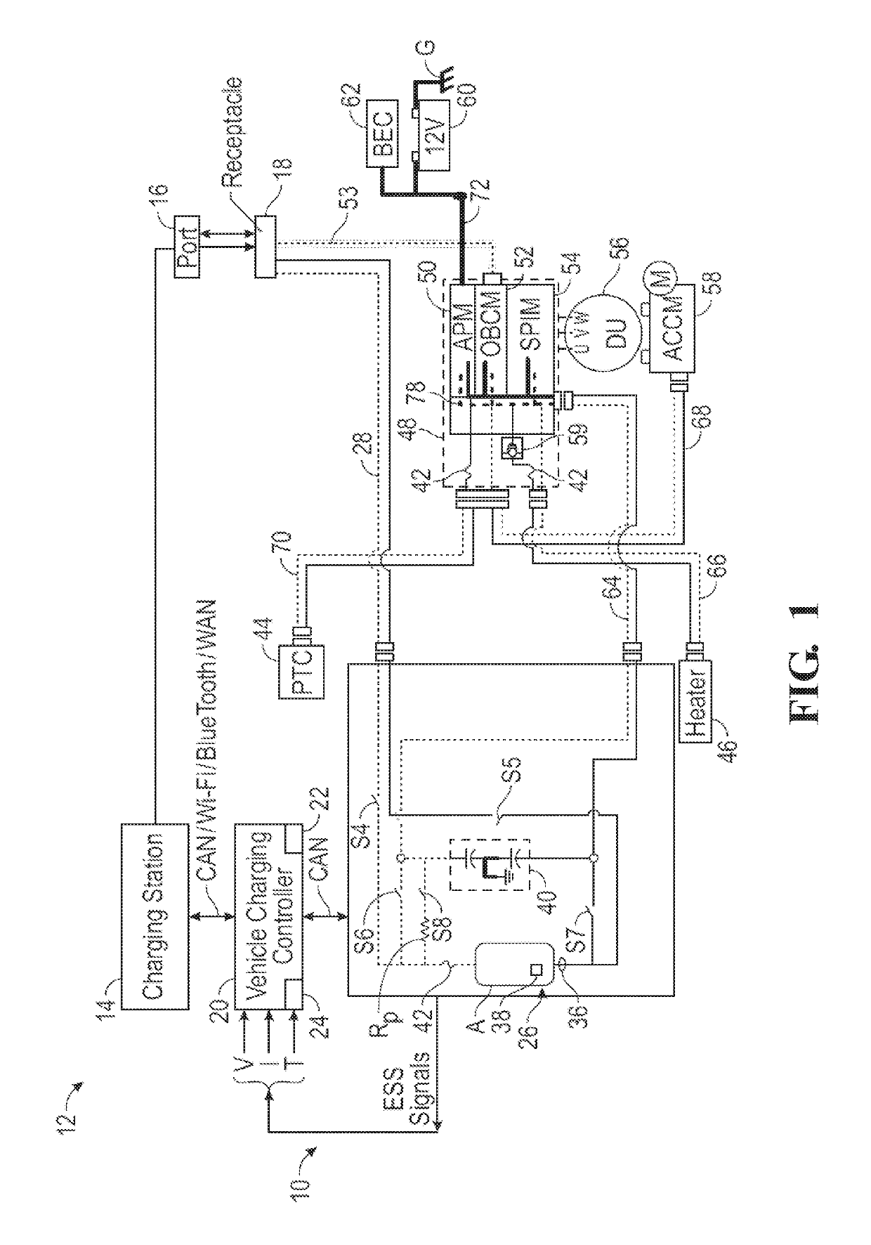
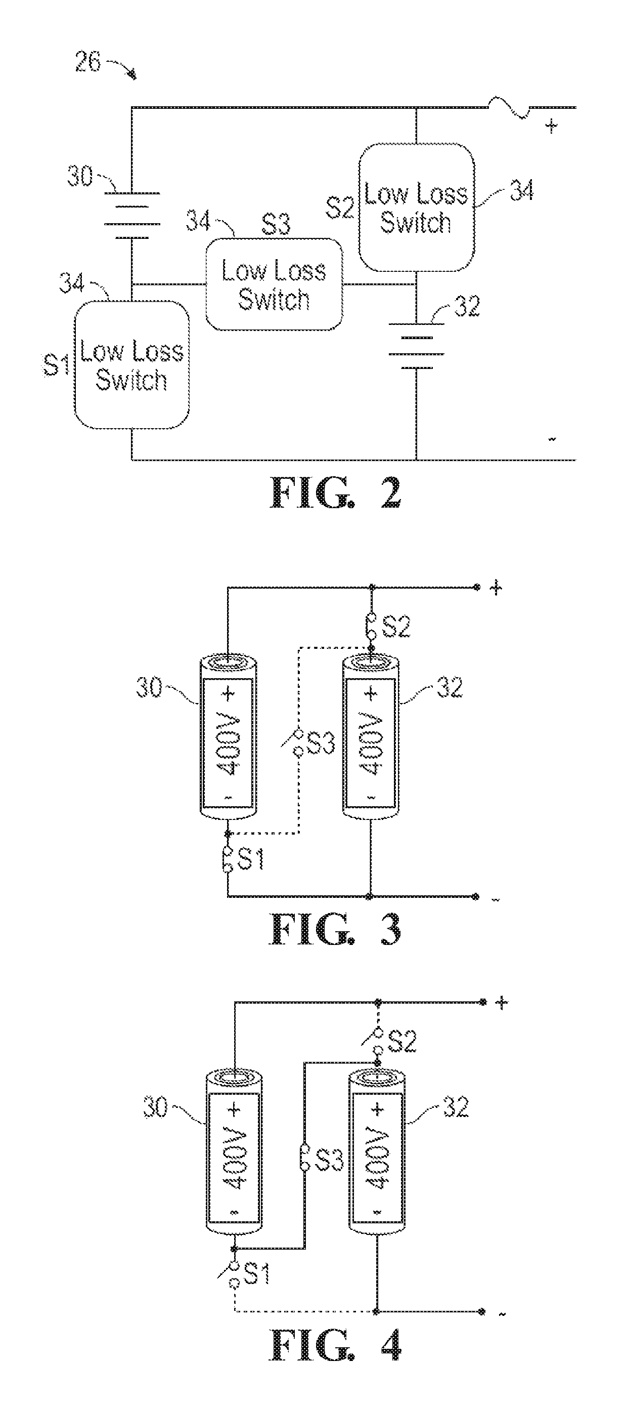
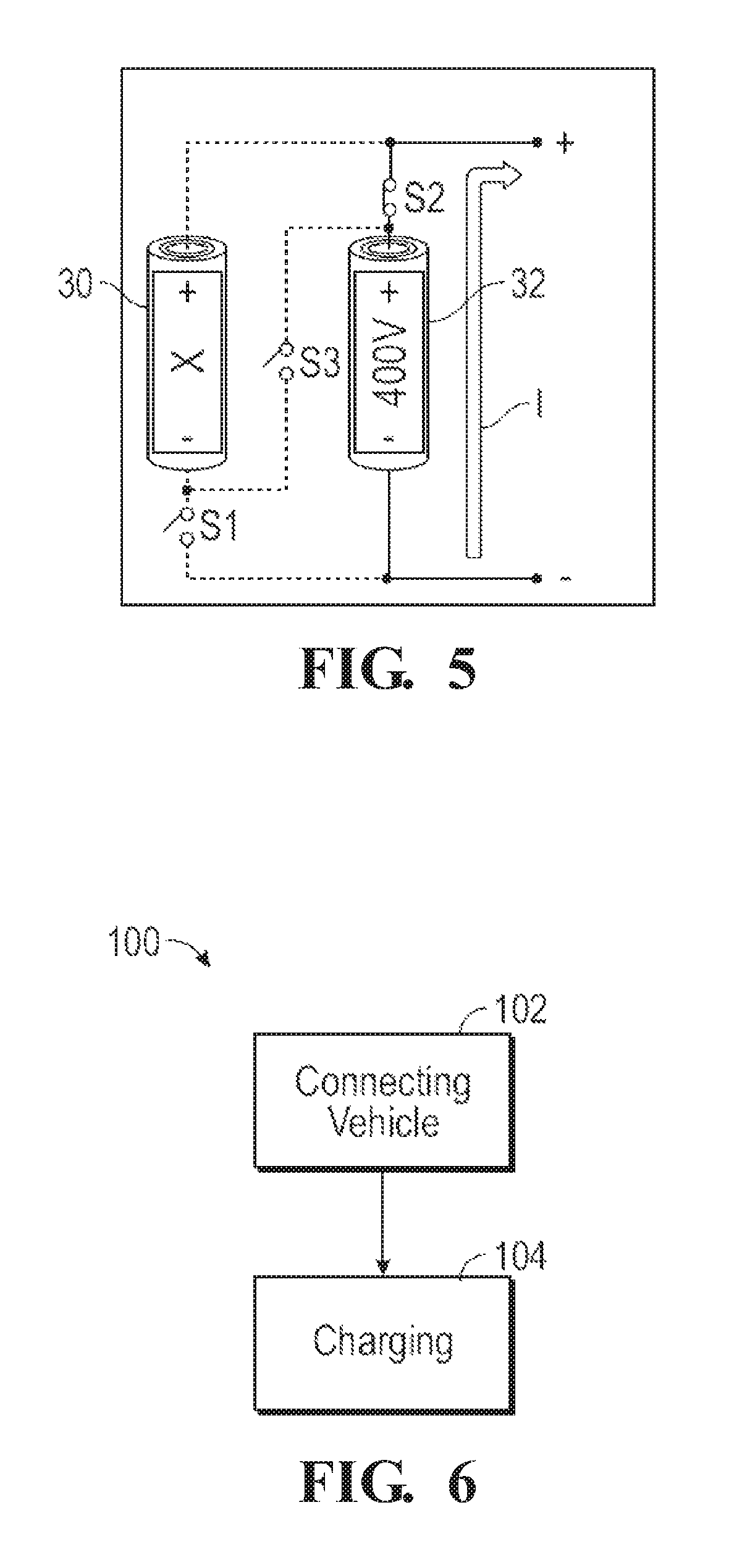
[0014]Accordingly, the energy storage system is capable of providing the electric current to the inverter at different voltages, e.g., a lower voltage and a higher voltage. The energy storage system may be controlled to provide the electric current at the lower voltage when the electric machine is operating at a lower rotational speed in order to reduce energy losses in the system. The energy storage system may be controlled to provide the electric current at the higher voltage when the electric machine is operating at higher rotational speeds to enable the electric machine to generate more torque.

Problems solved by technology

The torque producing ability of the electric powertrain at high rotational speeds of the electric machine is limited by the voltage output from the energy storage system.
However, the higher voltage output from the energy storage system generates higher energy losses in the electric powertrain at lower rotational speeds of the electric device.

Method used


Image

  • Electric powertrain and a method of operating the same
  • Electric powertrain and a method of operating the same
  • Electric powertrain and a method of operating the same

Examples


first embodiment

[0062]Referring to FIG. 10 for the energy storage system 126, the controller 148 senses a current rotational speed of the electric machine 122. The step of sensing the current rotational speed of the electric machine is generally indicated by box 160 in FIG. 10. The controller 148 may sense the rotational speed of the electric machine 122 in a suitable manner, such as with a rotational speed sensor or some other similar device. The controller 148 then compares the current rotational speed of the electric machine 122 to a first defined threshold, to determine if the current rotational speed of the electric machine 122 is less than the first defined threshold. The step of determining if the current rotational speed of the electric machine 122 is less than the first defined threshold is generally indicated by box 162 in FIG. 10.

[0063]When the controller 148 determines that the current rotational speed of the electric machine 122 is less than the first defined threshold, generally indic...

second embodiment

[0079]When the energy storage system 126 includes the energy storage system 126 described above, in which the first switching device 138, the second switching device 140, and the third switching device 142 each include a bi-directional blocking switch 144, then controlling the first switching device 138, the second switching device 140, and the third switching device 142 to operate in the first operating mode includes controlling the first switching device 138 into its respective on-state and the second switching device 140 and the third switching device 142 into their respective off-state to isolate the second energy storage device 132, such that the first energy storage device 130 supplies the electric current at the first system voltage, with the first system voltage being substantially equal to the first device voltage V1, thereby providing a lower system voltage.

[0080]When the energy storage system 126 includes the second embodiment of the energy storage system 126 described ab...


PUM


Abstract

An electric powertrain includes an electric machine, an inverter connected to the electric machine, and an energy storage system for providing an electric current. The energy storage system includes a first energy storage device operable at a first device voltage, and a second energy storage device operable at a second device voltage. A plurality of low-loss switching devices interconnect the first energy storage device and the second energy storage device. The switching devices are selectively controllable between a first operating mode for providing the electric current at a first system voltage, and a second operating mode for providing the electric current at a second system voltage. The first system voltage is different from the second system voltage.

Description

CROSS-REFERENCE TO RELATED APPLICATIONS[0001]This application is a continuation in part of U.S. patent application Ser. No. 15 / 824,525, filed on Nov. 28, 2017, the disclosure of which is hereby incorporated by reference.INTRODUCTION[0002]The disclosure generally relates to an electric powertrain.[0003]An electric powertrain includes an electric machine, such as but not limited to, an electric motor, and an energy storage system, such as but not limited to, a battery. The electric machine uses electric energy from the energy storage system to generate torque and provide a rotational output. The rotational output from the electric machine may be used to power a device. For example, the rotational output from the electric machine may provide motive power for a vehicle.[0004]The torque producing ability of the electric powertrain at high rotational speeds of the electric machine is limited by the voltage output from the energy storage system. Torque output at higher rotational speeds ma...

Claims


Application Information

Patent Timeline
Patent Type & Authority Patents(United States)
IPC IPC(8): H02P27/06H02J7/00B60L50/51H02M7/537H02M1/08
CPCH02M1/08H02J7/0063H02M7/537B60L50/51H02P27/06B60L2210/40H02M7/5387B60L58/19B60L53/68B60L53/22Y02T10/72Y02T90/16Y02T10/7072Y02T10/92Y02T10/70Y02T90/14Y02T90/12
Inventor NAMUDURI, CHANDRA S.NEHL, THOMAS W.HAO, LEI
Owner GM GLOBAL TECH OPERATIONS LLC
Why Eureka
Try Eureka