RF shielded exam room of a magnetic resonance imaging system

a magnetic resonance imaging and exam room technology, applied in the field of magnetic resonance imaging, can solve the problems of complicated access to the examination tube, uncomfortable patients and staff, and complicated electrical shielding, and achieve good shielding capabilities and good ergonomics for operation

Active Publication Date: 2019-10-08
KONINKLJIJKE PHILIPS NV
View PDF29 Cites 1 Cited by
  • Summary
  • Abstract
  • Description
  • Claims
  • Application Information

AI Technical Summary

Benefits of technology

[0009]It is an object of the invention to provide an exam room shielding, a magnetic resonance imaging system comprising an exam room having a shielding and a system comprising a magnetic resonance imaging system and an additional treatment or diagnostic device located at an outer circumference of the tubular shielding device, which have good shielding capabilities and offer good ergonomics for operation, for maintaining the magnetic resonance imaging system, and for preparing and caring about patients located within an examination space of the magnetic resonance imaging system.

Problems solved by technology

Electromagnetic shielding becomes more complicated when an MR imaging system is used together with at least one other device, which has to be located in vicinity of the MR imaging system.
For the MR imaging system, the linac device is an important source of electromagnetic interferences and vice versa, since both devices generate RF irradiation during operation.
Furthermore, also the other device may require shielding from the electromagnetic irradiation generated by the MR imaging system.
Accordingly, access to the examination tube is rather complicated, especially when access to the examination tube is required alternately from the opposite ends thereof.
This is rather uncomfortable for patients and staff.
The separation of the space by the exam room shielding increases the effort for installation, maintenance, and repair.

Method used


Image

  • RF shielded exam room of a magnetic resonance imaging system
  • RF shielded exam room of a magnetic resonance imaging system
  • RF shielded exam room of a magnetic resonance imaging system

Examples


first embodiment

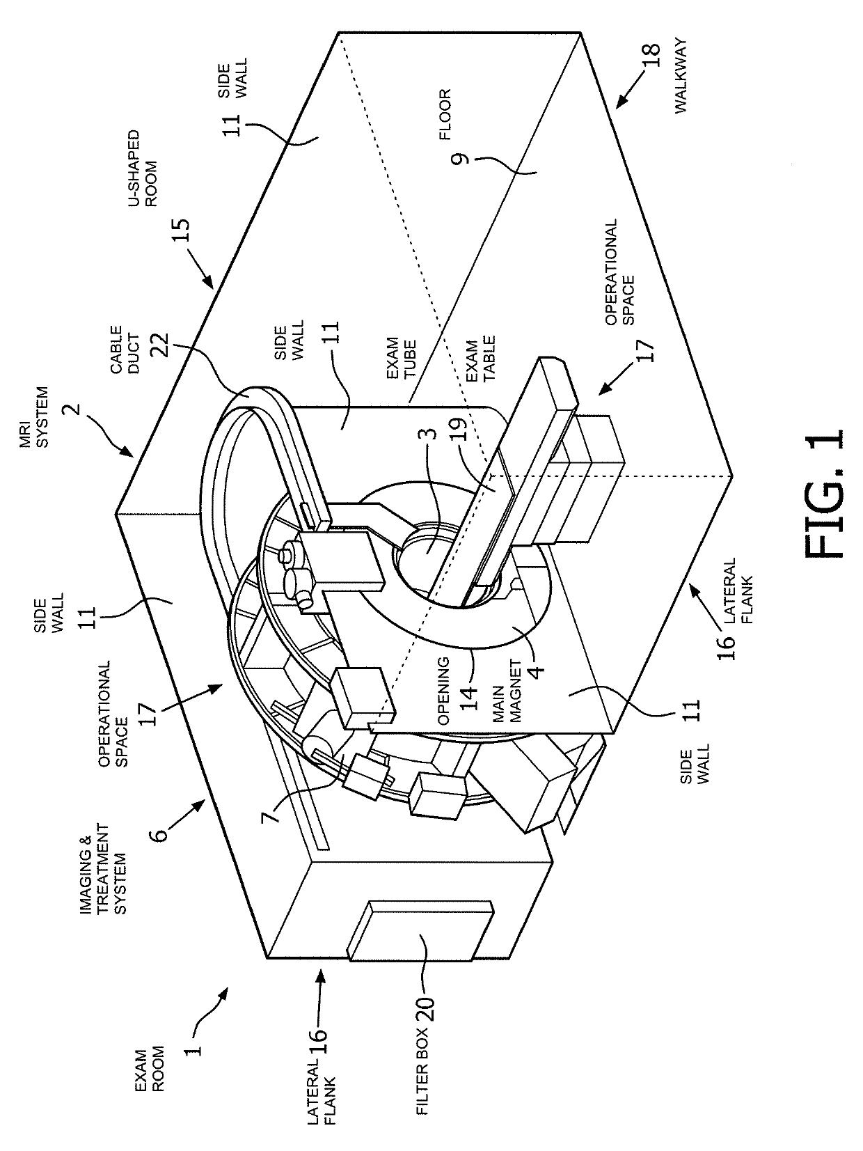
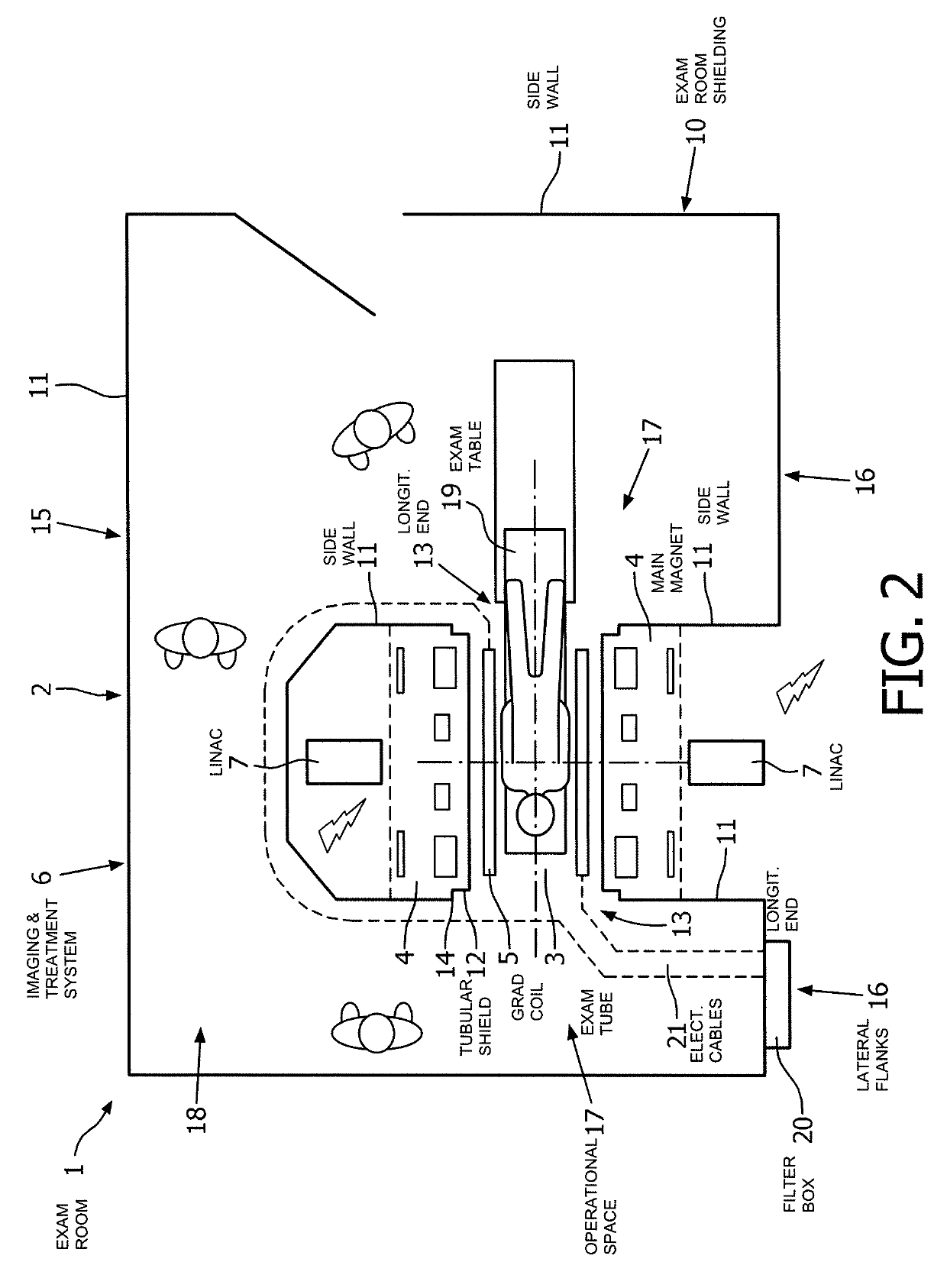
[0034]Starting from this general setup, which is shown in FIG. 2, the exam room shielding 10 further comprises a tubular shielding device 12, which is arranged to surround the examination tube 3 and the gradient coil assembly 5. The tubular shielding device 12 is made of an electrically conductive material as RF shield. The main magnet 4 and the linac device 7 are located at an outer circumference of the tubular shielding device 12. Both longitudinal ends 13 of the tubular shielding device 12 are circumferentially connected to openings 14 of the side walls 11 to provide an electrically conductive connection therebetween. Accordingly, a fully shielded compartment is formed within the exam room 1, where the examination tube 3 and the gradient coil assembly 5 as well as cables 21 are shielded from the main magnet 4 and the linac device 7.

second embodiment

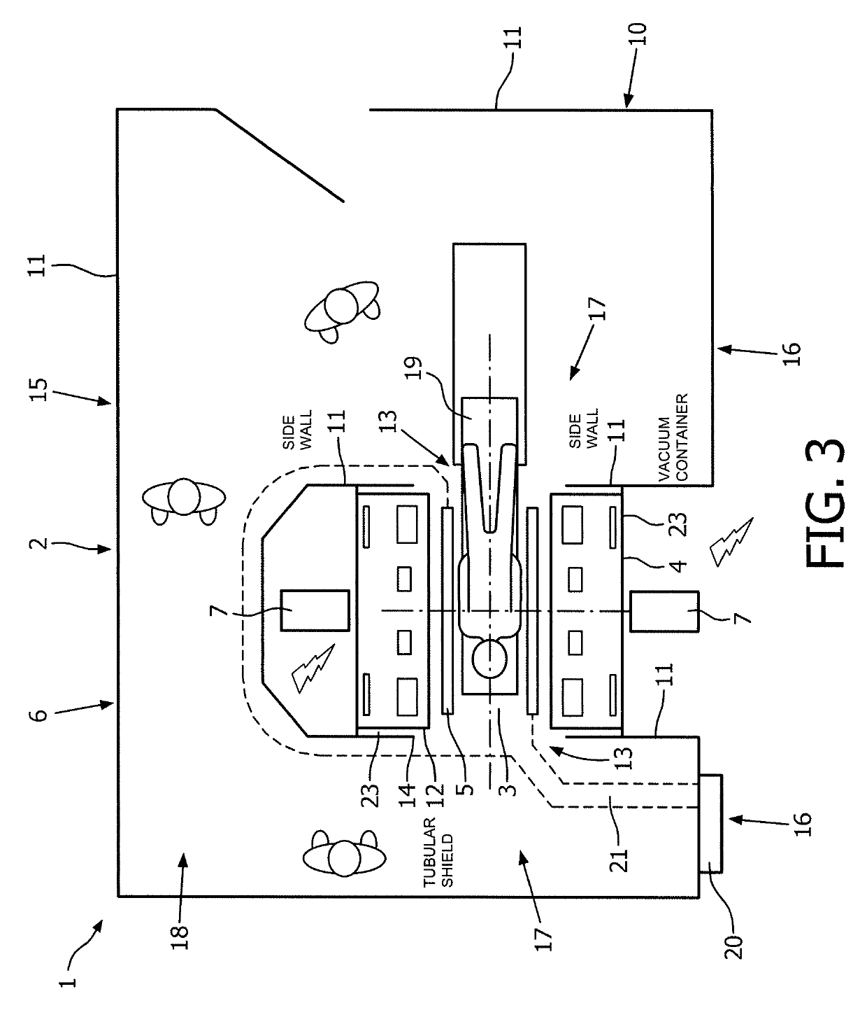
[0035]Starting again from the general setup, which is shown in FIG. 3, the exam room shielding 10 further comprises a tubular shielding device 12, which is provided integrally with the main magnet 4. The main magnet 4 is provided having an outer vacuum container 23, which is a thick-walled stainless-steel or aluminum structure. The side walls 11 of the lateral flanks 16 of the exam room shielding 10 extend over the entire circumferential flanges of the main magnet 4. The side walls 11 are electrically connected to the outer vacuum container 23 close to the outer radius of the flanges of the main magnet 4. Accordingly, a fully shielded compartment is formed within the exam room 1, where the examination tube 3 and the gradient coil assembly 5 are shielded from the main magnet 4 and the linac device 7, and the linac device 7 is shielded from the examination tube 3, the gradient coil assembly 5, and the main magnet 4


PUM


Abstract

An exam room shielding (10) for electromagnetically shielding a magnetic resonance imaging system (2) includes: a ceiling, a floor, side walls (11) interconnecting the ceiling and the floor, and a tubular shielding device (12), which is arranged to surround an examination tube (3) of the magnetic resonance imaging system (2). Both longitudinal ends (13) of the tubular shielding device (12) are circumferentially connected to openings (14)of the side walls (11) which form the outline of an U-shaped room (15) with the longitudinal ends (13) of the tubular shielding device (12) interconnecting the lateral flanks (16) of the U-shaped room (15). A magnetic resonance imaging system (2) includes an exam room (1), with the above exam room shielding (10). An additional treatment or diagnosis device (7) can be located at an outer circumference of the tubular shielding device (12). This separates the space inside the exam room into a compartment free of RF noise, i.e. the space surrounded by the exam room shielding, for MR scanning, and a compartment outside the shielding, in which an operator can move for operating the MR imaging system and / or preparing a person for a MR scan.

Description

CROSS REFERENCE TO RELATED APPLICATIONS[0001]This application is a U.S. national phase application of International Application No. PCT / EP2014 / 060719, filed on May 23, 2014, which claims the benefit of EP Application Serial No. 13170802.6 field on Jun. 6, 2013 and is incorporated herein by reference.FIELD OF THE INVENTION[0002]The invention relates to the field of magnetic resonance (MR) imaging, in particular in conjunction with the use of diagnostic or treatment devices like linear accelerator devices or others.BACKGROUND OF THE INVENTION[0003]Electromagnetic shielding of a magnetic resonance (MR) imaging system is an important requirement for reliable operation thereof and a basis for generation of high quality diagnostic images. Such an electromagnetic shielding is provided as a Faraday cage to enable a shielding of RF irradiation. Accordingly, components of the MR imaging system involved in the generation or measurement of electromagnetic fields as well as components for analog...

Claims


Application Information

Patent Timeline
Patent Type & Authority Patents(United States)
IPC IPC(8): A61B5/00G01R33/422G01R33/48A61B5/055G21F7/00G01R33/28G01R33/385
CPCA61B5/0046A61B5/055G21F7/00G01R33/422G01R33/288G01R33/385G01R33/4808
Inventor OVERWEG, JOHANNES ADRIANUSUHLEMANN, FALK
Owner KONINKLJIJKE PHILIPS NV
Why Eureka
Try Eureka