Accommodative intraocular lens that ejects post capsular opacification and self-centers

a technology of intraocular lens and haptic, which is applied in the field of accommodating intraocular lens having a haptic, can solve the problems of brittle hydrophilic materials and loss of potential accommodation, and achieve the effect of reducing potential warpage of optics

Inactive Publication Date: 2019-10-15
CALLAHAN WAYNE B
View PDF19 Cites 0 Cited by
  • Summary
  • Abstract
  • Description
  • Claims
  • Application Information

AI Technical Summary

Benefits of technology

[0011]Embodiments of the invention provide an accommodating intraocular lens with a bi-convex, bi-aspheric, smooth surfaced optic held inside an anterior annulus via tabs. A second larger diameter posterior annulus is positioned posteriorly and connects via a sloped surface to where the annuluses are at a maximum separation when viewing NEAR objects and minimum separation in the FAR position. The sloped surface is cut into ribbons, tabs and / or additional annuluses without pushing the surfaces into the capsule when implanted; therefore, only the anterior and posterior annuluses have a force component against the capsule. The proximal edge of the anterior annulus is anterior to the apex of the anterior surface of the optic. The anterior capsule resting on the anterior annulus leaves space for hydration of the capsule. It also reduces potential warpage of the optic. The anterior annulus edge is designed to scrape PCO from the capsule. When changing accommodative states, aqueous turbulence will increase the removal of PCO. The posterior annulus and capsule squeeze PCO when moving from the FAR to NEAR positions. Once saturated with aqueous fluid the PCO can be carried out of the eye via natural physiological processes.
[0012]In embodiments, the annuluses are held together via tabs attached to ribbons which are cut into the haptic slope forming the equivalent of complex cantilevered beams. The ribbons can be parallel to (or concentric with—depending on whether the device is in a relaxed or compressed state) the anterior and posterior annuluses or angled. The tabs can also be attached to additional annuluses. When the intraocular lens is implanted, the anterior and posterior annuluses in contact with the segments of the capsule stretch each segment tight. With tight capsular segments and differential pressures the vitreous pressure is higher than the aqueous for NEAR vision and the reverse for distant vision. The differential pressures allow the optic to be held in position. If the surgeon refracts the patient slightly hyperopic the optic is expected to stop at emmetropia. For lenses manufactured with stiffer materials, the lens can be squeezed until collapsed and expected to remain in such a state long enough for implantation using only forceps. Forces placed on the anterior and posterior annuluses via capsule remnants will force centration of the lens without surgical assistance.
[0016]Aspect 4 is the lens in any one of Aspects 1-3 where the optic is bi-aspheric with smooth surfaces that can vary in power to reduce the profile of the lens to allow more travel space for accommodation.
[0019]Aspect 7 is the lens in any one of Aspects 1-6 where the anterior capsule rest against the apex of the anterior annulus preventing warpage of the optic.

Problems solved by technology

Hyperopia—Condition of the eye where the natural lens does not automatically compensate by increasing the power needed by the patient for clear vision.
Some potential accommodation will be lost; however, significant accommodation should still be available as only a small portion of the potential movement should be needed for sizing.
Prior to hydration the hydrophilic materials are brittle.
Contamac also has an 18% water content material that is stiffer and not popular because the material opens slowly causing the surgeon delay for centration.

Method used


Image

  • Accommodative intraocular lens that ejects post capsular opacification and self-centers
  • Accommodative intraocular lens that ejects post capsular opacification and self-centers
  • Accommodative intraocular lens that ejects post capsular opacification and self-centers

Examples


Embodiment Construction

[0095]Reference will now be made in detail to various exemplary embodiments of the invention. It is to be understood that the following discussion of exemplary embodiments is not intended as a limitation on the invention. Rather, the following discussion is provided to give the reader a more detailed understanding of certain aspects and features of the invention.

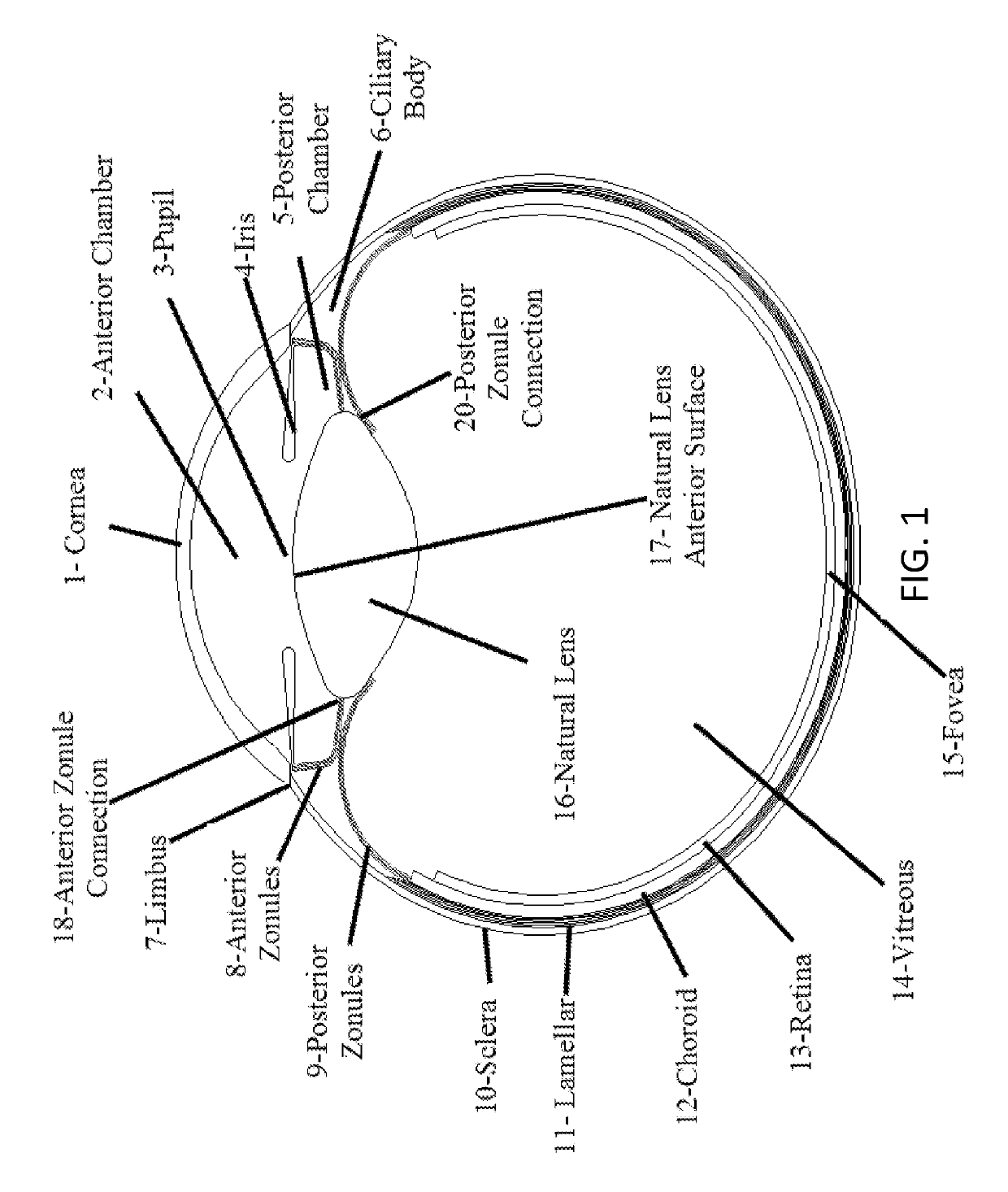
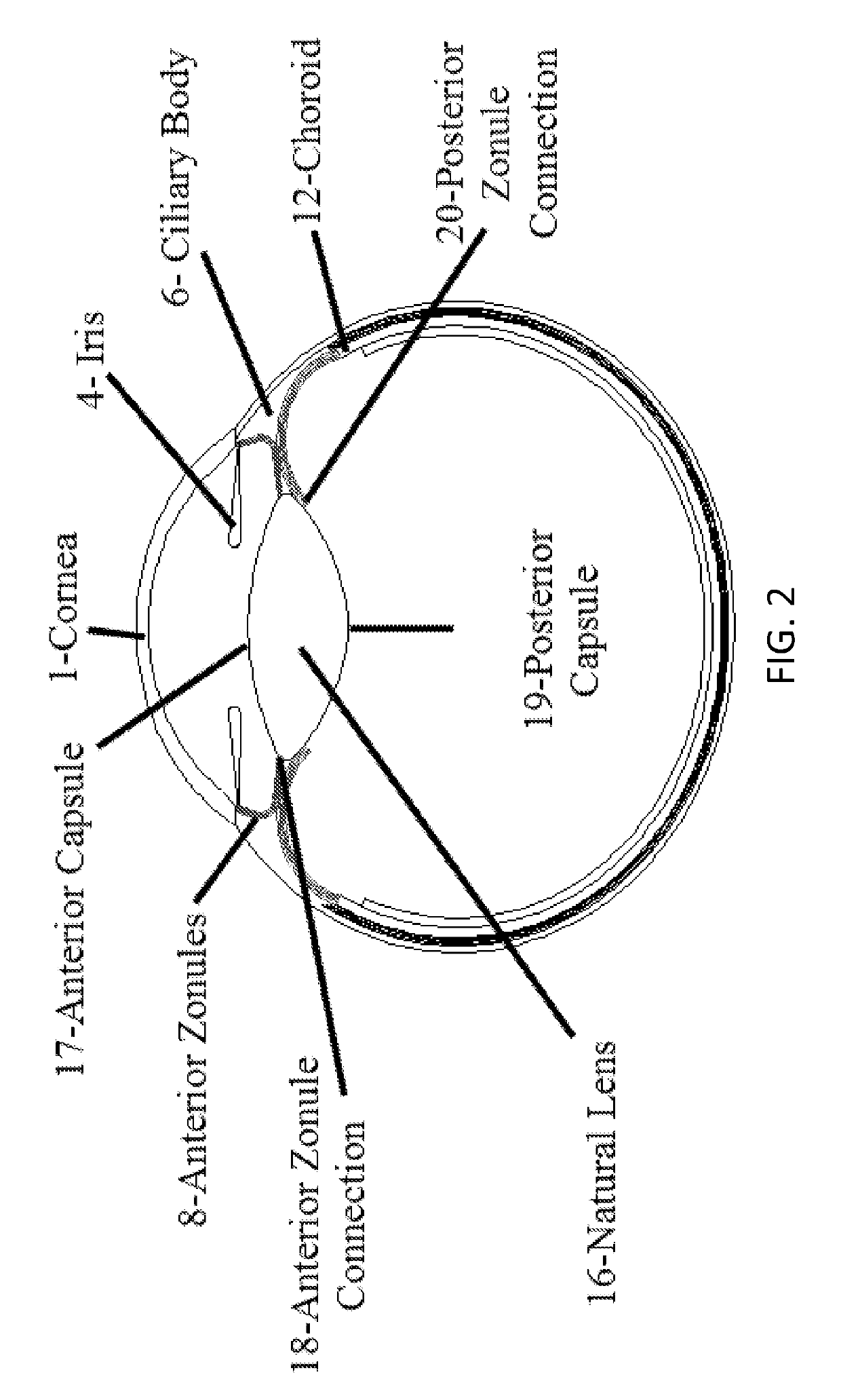
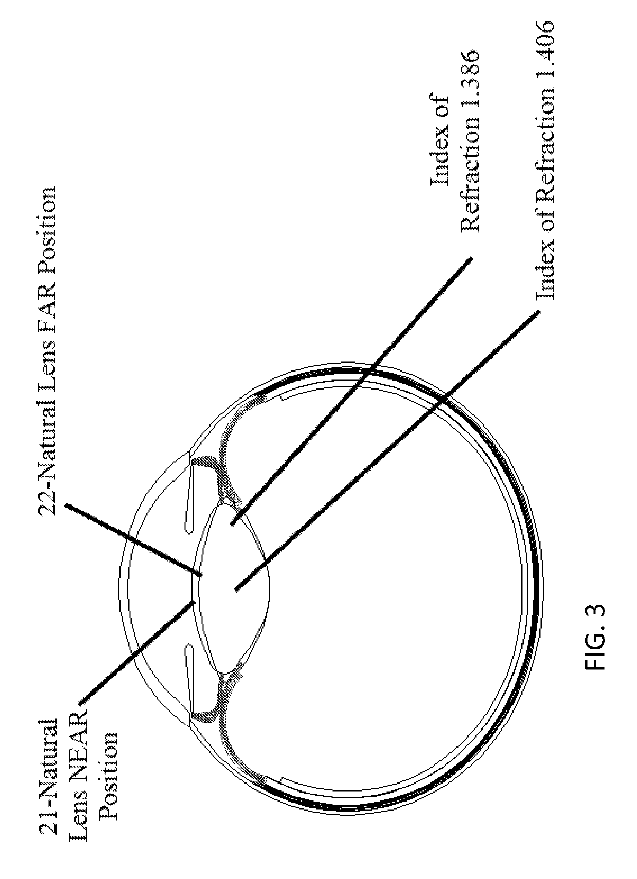
[0096]Unless otherwise noted, definitions for ocular terminology included in this specification can be found in the Dictionary of Eye Terminology by Barbara Cassin and Melvin L. Rubin (ISBN 0-937404-44-6); Merriam Webster's Medical Dictionary (ISBN 0-87779-914-8); or American Heritage College Dictionary Fourth Addition (ISBN-13; 978-0-618-8359-9 ISBN-10; 0-618-83595-4). Other references that may provide background to the invention include Fundamentals of Optics—by Francis Jenkins & Harvey E. White (ISBN 0-07-032330-3) and Optical Engineering Fundamentals by Bruce H. Walker (ISBN-13: 978-0819475404; ISBN-10: 0819475408). Each...


PUM


Abstract

Described is an accommodating intraocular lens with a bi-convex, bi-aspheric, smooth surfaced optic held inside an anterior annulus via tabs. A second larger diameter annulus is positioned posteriorly and connects via a sloped surface to where the annuluses are at a maximum separation when viewing NEAR objects and minimum separation in the FAR position. The sloped surface is cut into ribbons, tabs and / or other annuluses without pushing the surfaces into the capsule when implanted; therefore, only the anterior and posterior annuluses have a force component against the capsule. The proximal edge of the anterior annulus is anterior to the apex of the anterior surface of the optic. The anterior capsule resting on the annulus leaves space for hydration of the capsule and reduces potential warpage of the optic. The annulus edge is designed to scrape posterior capsular opacification from the capsule.

Description

BACKGROUND OF THE INVENTIONField of the Invention[0001]The present invention relates generally to intraocular lenses and more specifically to an accommodating intraocular lens having a haptic comprising two or more annuluses connected together by one or more ribbons or tabs. The ribbons are disposed in parallel to the annuluses while the tabs are disposed radially to the annuluses. Together, the ribbons and tabs provide a spring-like capability to the haptic such that the annuluses are at a maximum separation when viewing NEAR objects and minimum separation when viewing FAR objects. The intraocular lens is useful for replacing natural lenses diseased by cataracts and other conditions.Description of Related Art[0002]Anatomy[0003]FIG. 1 shows the clear portion of the eye, cornea (1), and functions as the window to the remainder of the eye and refracts (bends) light. Just behind the cornea is the anterior chamber (2) filled with a clear watery, salty liquid (aqueous humor). At the back...

Claims


Application Information

Patent Timeline
Patent Type & Authority Patents(United States)
IPC IPC(8): A61F2/16
Inventor CALLAHAN, WAYNE B.
Owner CALLAHAN WAYNE B
Why Eureka
Try Eureka