Method for cancelling electric crosstalk in a printhead

a technology of printhead and crosstalk, applied in printing and other directions, can solve the problems of high level of electrical crosstalk between electric signals, small electric signals, pressure waves in ink, etc., and achieve the effect of reducing the necessary dynamic range or the number of bits of adc, more accurate, and better capabl

Active Publication Date: 2019-10-22
OCE HLDG BV
View PDF5 Cites 0 Cited by
  • Summary
  • Abstract
  • Description
  • Claims
  • Application Information

AI Technical Summary

Benefits of technology

[0010]The instantaneously received crosstalk in the first and second transducer being equal, which means that the crosstalk signal from the second transducer is proportional to the crosstalk signal in the first transducer, enables the possibility to directly subtract the crosstalk contribution in the monitoring signal, even before an analog-digital conversion (ADC) takes place. Since the electric crosstalk may be as large as or even (much) larger than the signal caused by an acoustic wave in the pressure chamber, this direct subtraction reduces the necessary dynamic range, or the number of bits, of the ADC. Compared to saving a crosstalk contribution at an earlier time as a reference, the invented method is more accurate and better capable of compensating for drift of the crosstalk signal.
[0011]In a further embodiment, the method is applied in an inkjet print head comprising an array of jetting units, a jetting unit comprising a pressure chamber attached to an electro-mechanical transducer. The electro-mechanical transducer is often a piezo-electric material in connection with a pressure chamber that is filled with ink. The ink is jetted in the form of a drop forming amount of ink from a nozzle at the end of the pressure chamber, if a sufficiently strong electric pulse, a jetting actuation signal, is applied to the piezo-electric transducer. The high density of jetting units with closely packed electrical leads in the print head, causes a high level of electrical crosstalk between the electric signals in various jetting units. By applying the invented method, a monitoring signal from one unit may be determined with less interference from the signals of other jetting units.
[0014]In a further embodiment, a third transducer is actuated with a jetting actuation signal. In operation, any third jetting unit may be actuated according to an intended scheme associated with the application of the jetting unit. Since the crosstalk is promptly subtracted, there is no need to wait for the jetting operation to be finished. As soon as two associated transducers are available, that means that they are ready for recording a monitoring signal, the method according to the invention may be applied. Thus, the method may be carried out while the device, e.g., the print head, is operating, so that the properties of the jetting devices can be monitored quasi continuously during the operation of the device.

Problems solved by technology

The high density of jetting units with closely packed electrical leads in the print head, causes a high level of electrical crosstalk between the electric signals in various jetting units.
A non-jetting actuation signal is not sufficiently strong to generate an ink drop form the jetting unit, but still causes a pressure wave in the ink in the pressure chamber.
This results in a rather small electric signal, at least compared to the crosstalk of jetting actuation signals for other jetting units.

Method used


Image

  • Method for cancelling electric crosstalk in a printhead
  • Method for cancelling electric crosstalk in a printhead

Examples


Embodiment Construction

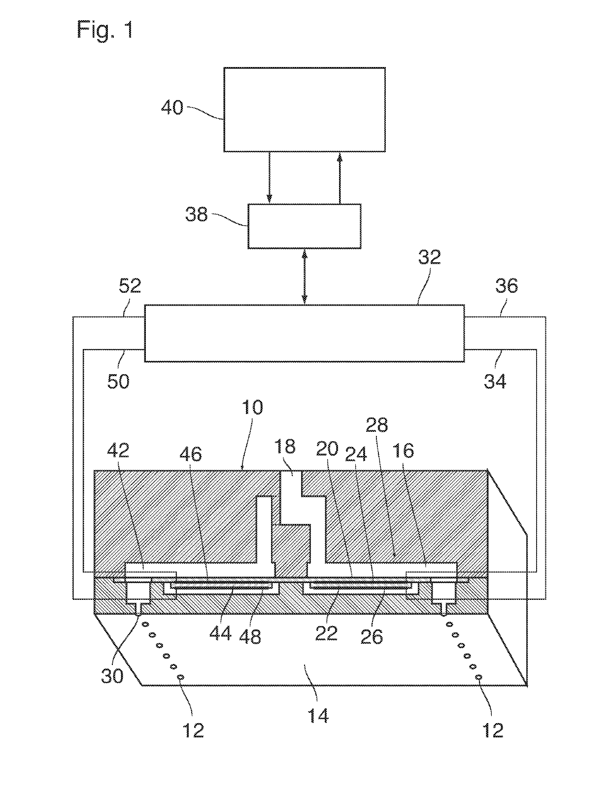
[0021]As is shown in FIG. 1, a droplet ejection device which may for example form part of an ink jet printer comprises a nozzle head 10 with plurality of nozzles 12 formed in a flat nozzle face 14. The nozzle head 10 may for example be formed by MEMS technology (Micro Electro Mechanical System).

[0022]Each nozzle 12 is connected to one end of a duct 16 that is filled with liquid ink. An opposite end of the duct 16 is connected to an ink supply line 18 that is common to all the nozzles 12 and ducts 16 of the entire nozzle head. One wall of each duct 16 is formed by a flexible membrane 20 to which an electro-mechanical transducer 22 is attached on the side outside of the duct 16. The transducer 22 has a number of electrodes 24 only two of which have been shown here. The transducer 22 may be a piezoelectric transducer with a plurality of layers of piezoelectric material stacked one upon the other and with internal electrodes intervening therebetween. The internal electrodes inside the p...


PUM


Abstract

A method is provided for cancelling an electric crosstalk contribution in a monitoring signal from a monitored electro-mechanical transducer in a device including at least three electro-mechanical transducers. The crosstalk contribution results from an actuation of other transducers than the monitored transducer. The method includes selecting a second transducer, associated with the first, monitored transducer, wherein the electric crosstalk caused by an actuation of a third transducer is equal in the first and second transducer; actuating the first transducer and not acutating the second transducer; simultaneously measuring a monitoring signal from the first transducer and the second transducer; and subtracting the two monitoring signals to obtain a clean monitoring signal from the first transducer.

Description

CROSS REFERENCE TO RELATED APPLICATIONS[0001]This application is a Continuation of PCT International Application No. PCT / EP2017 / 058275, filed on Apr. 6, 2017, which claims priority under 35 U.S.C. 119(a) to Patent Application No. 16165297.9, filed in Europe on Apr. 14, 2016, all of which are hereby expressly incorporated by reference into the present application.BACKGROUND OF THE INVENTION1. Field of the Invention[0002]The invention relates to a method for cancelling an electric crosstalk contribution in a monitoring signal from a monitored electro-mechanical transducer in a device comprising at least three electro-mechanical transducers which are driven by actuation signals, the crosstalk resulting from an actuation of other transducers than the monitored transducer. More particularly, the invention relates to a method for cancelling an electric crosstalk in monitoring signals from transducers of a jetting device such as an ink jet print head, wherein electric signals produced by t...

Claims


Application Information

Patent Timeline
Patent Type & Authority Patents(United States)
IPC IPC(8): B41J2/045B41J2/14
CPCB41J2/04525B41J2/04581B41J2/0451B41J2002/14354
Inventor SIMONS, JOHANNES M. M.
Owner OCE HLDG BV
Why Eureka
Try Eureka