
Dry powder inhaler

a technology of dry powder and inhaler, which is applied in the direction of inhalators, medical devices, atomisers, etc., can solve the problems of poor lung uptake, poor release of agglomerates, etc., and achieve the effect of reducing the swirl in the airflow

Active Publication Date: 2019-10-29
PRESSPART MFG
View PDF13 Cites 4 Cited by
  • Summary
  • Abstract
  • Description
  • Claims
  • Application Information

AI Technical Summary

Benefits of technology

[0017]As the outlet ducts are feed substantially parallel to the inner wall there is a smooth transition between the outlet ducts and the swirl chamber.
[0019]Preferably the swirl chamber comprises a dome like shape having a top, at which the swirl chamber outlet is located. Because of the conservation of the angular momentum the tangential velocity of the swirl increases when the inner wall of the swirl chamber tapers towards the swirl chamber outlet. Consequently as the swirl approaches the swirl chamber outlet the angular velocity increases thereby intensifying the swirl and the breakdown of the agglomerates. This results in shear forces on the agglomerates within the flow, helping to break them up. The dome shape therefore contributes to a more efficient break down of the agglomerates the medicament is contained in.
[0020]Advantageously the swirl chamber is rotationally symmetrical to a vertical axis along which the inner wall extends from the base. The rotationally symmetrical shape reduces the flow losses to a minimum.
[0021]According to an alternative embodiment the inner wall forms a polygon surrounding the base. The polygon shape improves the breakdown of the particles the medicament is contained in as they continuously collide with the inner wall on their way towards the swirl chamber outlet.
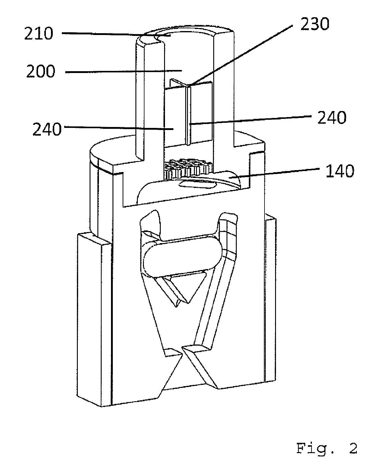
[0024]Preferably at least one plate is positioned in the mouthpiece duct, wherein the plate extends in flow direction of the airflow. The plate reduces the swirl in the airflow.
[0025]Also preferred is a cross formed by two plates arranged perpendicular to each other which is positioned in the mouthpiece duct, wherein the plates extend in flow direction of the airflow. The cross further reduces the swirl in the airflow.

Problems solved by technology

However, big agglomerates often show a poor release from the capsule and / or a poor lung uptake.

Method used


Image

  • Dry powder inhaler
  • Dry powder inhaler

Examples


Embodiment Construction

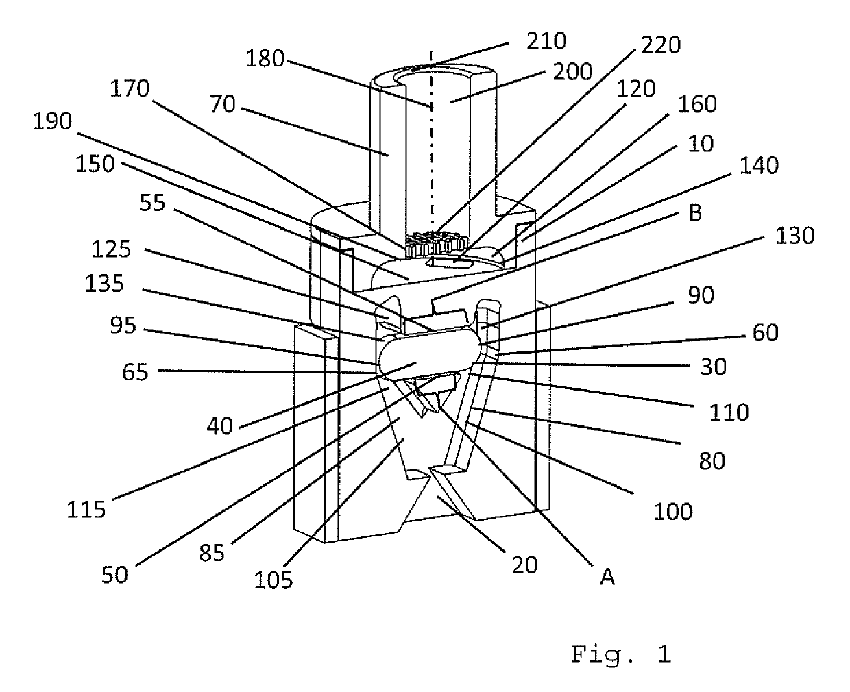
[0032]With reference to FIG. 1, a first exemplary embodiment of an inhaler device according to the present invention will be described.

[0033]The inhaler device comprises an inhaler housing 10 having one air inlet duct 20 through which ambient air flows into the inhaler device during inhalation. The inhaler further comprises an elongated capsule chamber 30 adapted for receiving a capsule 40 containing a dose of medicament in dry powder form. FIG. 1 shows an embodiment of the inventive inhaler device together with a capsule 40 inserted in the capsule chamber 30. The capsule 40 has a longitudinal axis and first and second end sections 90, 95 delimiting the capsule 40 on opposing ends. The capsule 40 further comprises a central, cylindrical section between said first and second end sections 90, 95.

[0034]The capsule chamber 30 has a longitudinal axis and is defined by a wall arrangement including a first and a second supporting wall portion 50, 55 opposing each other in a direction perpe...


PUM


Abstract

The present invention relates to an inhaler device for delivering a dose of medicament in dry powder form from a container to a patient in need thereof. The inhaler comprises a swirl chamber in which particles of the medicament entrained in an airflow swirl upon inhalation thereby breaking up the agglomerates into finest dispersed powder.

Description

[0001]The present invention relates to an inhaler device for delivering a dose of medicament in dry powder form from a container to a patient in need thereof.BACKGROUND OF THE INVENTION[0002]Inhalers are commonly used to deliver drugs into the lung of a patient in need thereof. Different types of inhalers have been developed and are available on the market, amongst which dry powder inhalers (DPIs) are becoming attractive in the treatment of various respiratory problems such as asthma, bronchitis or chronic obstructive pulmonary disease (COPD) and for the delivery of non-asthma drugs delivered via inhalation.[0003]In dry powder inhalers, the dose of medicament is present in dry powder form and usually pre-packed in a capsule. Blister-based dry powder inhalers are also known.[0004]In capsule-based dry powder inhalers, a capsule is placed into a capsule chamber of the inhaler before inhalation and opened, e.g. by piercing the capsule at its ends. Subsequently, the patient inhales throu...

Claims


Application Information

Patent Timeline
Patent Type & Authority Patents(United States)
IPC IPC(8): A61M15/00A61M11/00
CPCA61M11/00A61M15/0021A61M15/0005A61M15/0041A61M2202/064A61M2206/16A61M15/0028A61M11/003A61M2206/11
Inventor HEMY, JULIANTURNER, RICHARDSCHMELZER, HANS-PETERSCHMITZ, DIETMARHOFFMANN, STEFANSULE, AMEETSULE, SUNITASEILER, MATTHIASBOSTOCK, GEORGE ALEXANDEREINARI LAAKSO, AKI HANNUWORTH, MICHAELSCHUMANN, MATTHEW
Owner PRESSPART MFG
Learn More