Unlock instant, AI-driven research and patent intelligence for your innovation.

Composite embedded voltage regulator (CEVR)

a voltage regulator and composite technology, applied in the field of power supplies, can solve the problems of large drop in voltage, poor output regulation, high power consumption, etc., and achieve the effect of more efficient components and greater efficiency

Inactive Publication Date: 2019-10-29
NANOHENRY INC
View PDF13 Cites 0 Cited by
  • Summary
  • Abstract
  • Description
  • Claims
  • Application Information

AI Technical Summary

Benefits of technology

The present invention is a composite voltage regulator for driving voltage regulation on a combinatory chip, which includes an off-die current controlled bulk current source and an embedded voltage regulator (EVR) for controlling voltage regulation. The EVR is a multiphase switch-mode power supply buck or buck-boost, and operates at a faster switching frequency and longer duty cycle than the bulk current source. The EVR has lower output supply impedance than the bulk current source. The method involves supplying auxiliary current from the bulk current source to the functional unit in response to the current control signal generated from the EVR. The composite voltage regulator allows for more efficient and effective voltage regulation in combination with the off-die current controlled bulk current source. The technology improves thermal management and overvoltage protection.

Problems solved by technology

This leads to relatively large voltage drops, higher power consumption, and large printed circuit board (PCB) tracks, and can result in poor output regulation.
The power supply integrity requirements of modem high performance system-on-chips (SoCs) are extremely challenging in terms of loads and slew rates.
Conventional POL solutions are no longer able to meet those needs.
The main problem being that the impedance of the power delivery network (PDN) is too high to meet the voltage stability requirements.
In the SoC, the CPUs are loads that typically have a complex and dynamic impedance, meaning that the current draw is “as required”.
First, an extra thermal burden is created on the SoC and, second, because the EVR adds another regulator in series with the load, a generally lower overall conversion efficiency results.
The added thermal load results from the energy losses of the EVR.
Most of the EVR loss occurs on the SoC die, with the rest of the loss occurring in the inductors, which adds to the package thermal load.
These energy losses are primarily from the AC energy needed to turn on and off the inductor switches and the DC conduction losses of those switches, inductors, and connections.
If the EVR was 90% efficient, which is difficult to achieve, the result would be an on-die power dissipation increase of over 10%.
The problem is slightly non-linear and worsens, as a percentage, as power levels reach their maximum.
The EVR power dissipation represents a larger thermal burden on the SOC silicon substrate, which triggers thermal mitigation mechanisms sooner than non-EVR systems.
Regarding the overall system efficiency, EVR solutions are challenged by the losses of the switches, but mainly due to the need of the off-chip first stage regulator to provide the compatible input voltage to the EVR.
First, given that the SoC is in a nanometer process, a very low series resistance is hard to achieve.
A large number of interlevel metal layers means a large number of via stacks, and extremely large metal dimensions are needed to obtain low resistances low.
These high AC and DC losses make it difficult for EVR solutions to achieve even 88% efficiency.

Method used


Image

  • Composite embedded voltage regulator (CEVR)
  • Composite embedded voltage regulator (CEVR)
  • Composite embedded voltage regulator (CEVR)

Examples


Embodiment Construction

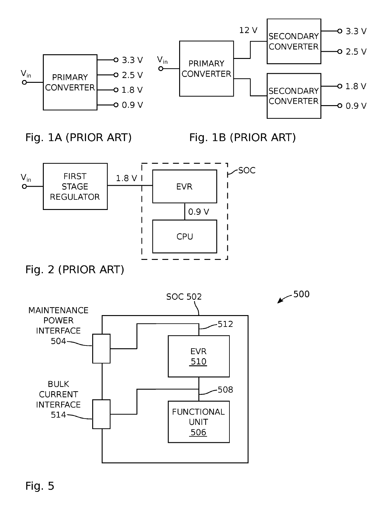
[0031]FIG. 5 is a schematic block diagram depicting a composite embedded voltage regulator (CEVR). The CEVR 500 comprises a system-on-chip (SoC) 502. As used herein, a SoC is a system of connected electrical circuits fabricated on a single, one-piece die or substrate, which is typically a silicon material, but may alternatively be another semiconductor material such as silicon-germanium (SiGe) for example. The SoC 502 may also be referred to as an integrated circuit (IC). As such, the single substrate and SoC are both represented by reference designator 502. The SoC 502 has a maintenance power interface 504 and a functional unit 506 (e.g., a central processing unit (CPU)) formed on the substrate, having an input supply on line 508 to accept power. Although not shown, the functional unit may comprise a group of CPU cores sharing the same input supply. When operating at top speed a typical CPU can only operate in a narrow range of voltages. For example, a voltage of 1.1 volts may caus...


PUM


Abstract

A system and method are provided for supplying bulk current to a voltage regulator embedded on a system-on-chip (SoC). An embedded voltage regulator (EVR) supplies a regulated voltage to a functional unit, the current demand is determined, and a current control signal is generated. An off-SoC bulk current source accepts the current control signal and supplies auxiliary (bulk) current to the functional unit in response to the current control signal. For example, in a first period of time a dynamic increase demand for a first current. Initially the EVR supplies the first current and creates an increase in SoC thermal loading. Subsequently, the EVR supplies a current less than the first current while the bulk current source supplies the bulk of the current. As a result, the bulk current source creates an off-SoC thermal load.

Description

RELATED APPLICATIONS[0001]Any and all applications, if any, for which a foreign or domestic priority claim is identified in the Application Data Sheet of the present application are hereby incorporated by reference under 37 CFR 1.57.BACKGROUND OF THE INVENTION1. Field of the Invention[0002]This invention generally relates to power supplies and, more particularly, to a system-on-chip (SoC) embedded voltage regulator (EVR) with an off-chip auxiliary bulk current source (BCS).2. Description of the Related Art[0003]Recent years have seen a move away from centralized alternating current (AC)-to-direct current (DC) power supplies to decentralized (distributed) power systems that use DC-to-DC converters near their point of use. The major driving force has been the decrease in core voltages. These low voltages at high currents are forcing the power conversion industry to reevaluate conventional circuit topologies, component selection, and packaging concepts. The point of load (POL) or point...

Claims


Application Information

Patent Timeline
Patent Type & Authority Patents(United States)
IPC IPC(8): H02M3/158G06F1/28G05F1/46H02M3/156H02M1/00
CPCH02M3/1584G05F1/465G06F1/28H02M2003/1566H02M2001/0009H02M2001/0045H02M3/1582G06F1/26G06F1/206G06F1/3243G06F1/3296Y02D10/00H02M3/1566H02M1/0009H02M1/0045
Inventor BRUNOLLI, MICHAEL
Owner NANOHENRY INC