Supercharge Your Innovation With Domain-Expert AI Agents!

Wheel cap section chamfering device

a chamfering device and wheel cap technology, applied in the field of burr cleaning, can solve problems such as unqualified appearance, and achieve the effects of improving production efficiency, reducing labor intensity of workers, and improving chamfering precision of the cap section

Active Publication Date: 2019-11-05
CITIC DICASTAL
View PDF7 Cites 0 Cited by
  • Summary
  • Abstract
  • Description
  • Claims
  • Application Information

AI Technical Summary

Benefits of technology

Automatically removes burrs with improved precision, reduces labor intensity, and enhances production efficiency while ensuring consistent chamfer angles and appearance quality.

Problems solved by technology

In actual production, the chamfers at the burr part are mostly manually removed, so the removal effect is not ideal, the roundness is poor, and the chamfers are not consistent in size and angle; and when a cap is mounted, the appearance is not qualified.

Method used


Image

  • Wheel cap section chamfering device
  • Wheel cap section chamfering device
  • Wheel cap section chamfering device

Examples


Embodiment Construction

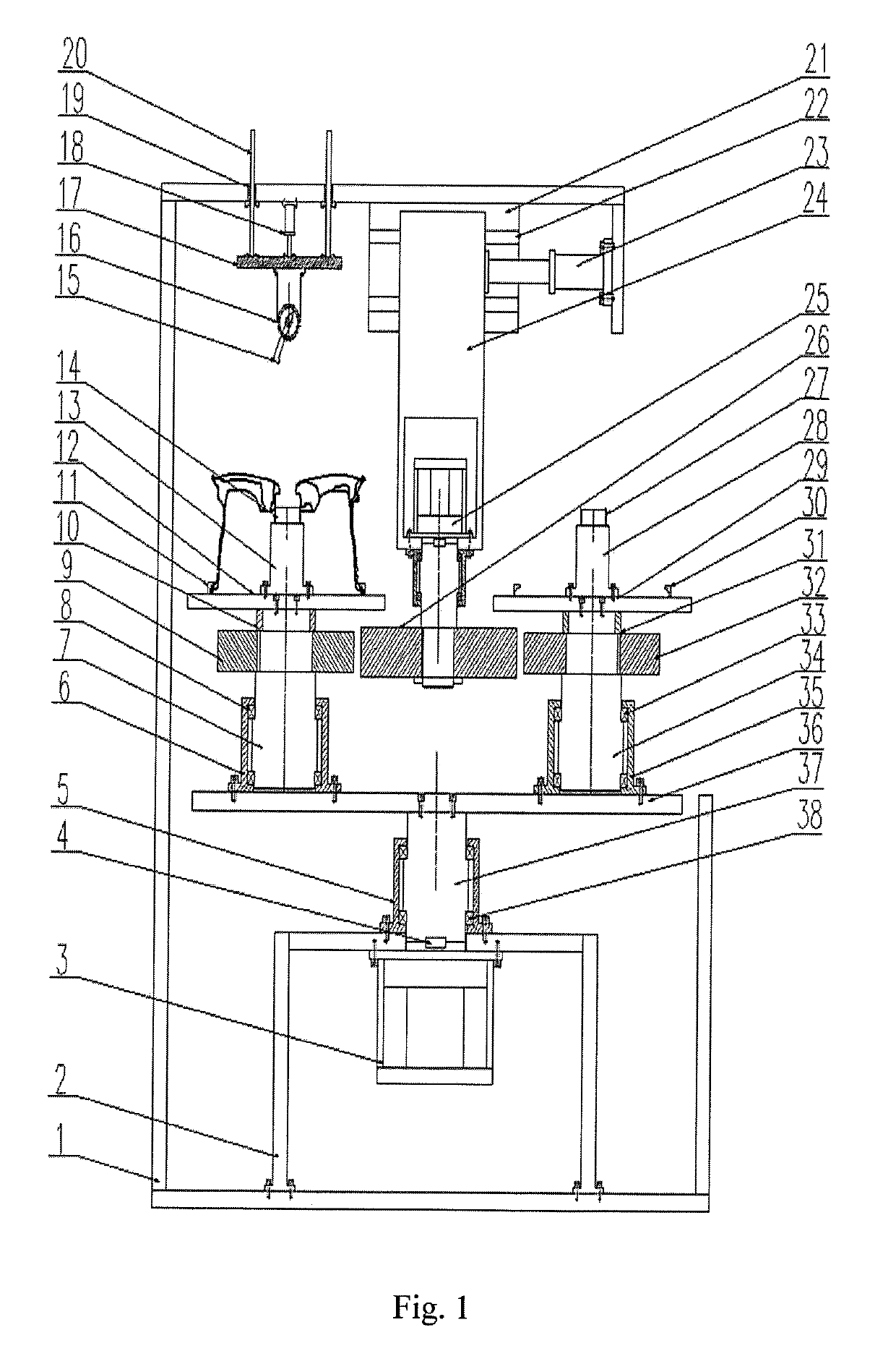
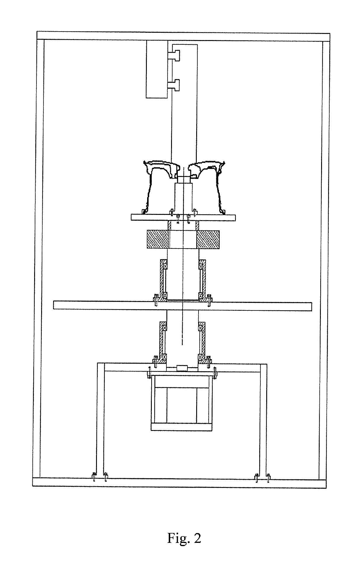
[0017]Details and working conditions of a specific device provided by the present application will be given below in combination with the accompanying drawings.

[0018]A wheel cap section chamfering device comprises a main frame 1, a secondary frame 2, a lower servo motor 3, a key 4, a bearing seat 5, a left bearing seat 6, a left shaft 7, a left bearing 8, a left driven friction wheel 9, a left sleeve 10, left corner cylinder pressure claws 11, a left turntable 12, a left mandrel seat 13, a left mandrel 14, a chamfer mill 15, a tool apron 16, a feeding platform 17, a feeding cylinder 18, guide sleeves 19, guide posts 20, a support plate 21, guide rails 22, a compression cylinder 23, a translation sliding table 24, an upper servo motor 25, a driving friction wheel 26, a right mandrel 27, a right mandrel seat 28, a right turntable 29, right corner cylinder pressure claws 30, a right sleeve 31, a right driven friction wheel 32, a right bearing 33, a right shaft 34, a right bearing seat ...


PUM

PropertyMeasurementUnit
speedaaaaaaaaaa
depthaaaaaaaaaa
sizeaaaaaaaaaa

Abstract

Disclosed is a wheel cap section chamfering device, comprising a main frame, a secondary frame, a lower servo motor, a key, a bearing seat, a left bearing seat, a left shaft, a left bearing, a left driven friction wheel, a left sleeve, left corner cylinder pressure claws, a left turntable, a left mandrel seat, a left mandrel, a chamfer mill, a tool apron, a feeding platform, a feeding cylinder, guide sleeves, guide posts, a support plate, guide rails, a compression cylinder, a translation sliding table, an upper servo motor, a driving friction wheel, a right mandrel, a right mandrel seat, a right turntable, right corner cylinder pressure claws, a right sleeve, a right driven friction wheel, a right bearing, a right shaft, a right bearing seat, a station rotating platform, a shaft and a bearing.

Description

CROSS-REFERENCE TO RELATED APPLICATIONS[0001]This application claims priority to Chinese Patent Application No. 201710598333.2, filed on Jul. 21, 2017, which is hereby incorporated by reference in its entirety.TECHNICAL FIELD[0002]The present application relates to the technical field of burr cleaning, specifically to a device for automatically removing burrs from chamfers at a cap section of a wheel.BACKGROUND ART[0003]For a fully coated hub having the front side not machined, the front side of a cap section is cast, and the depth of the cap section is turned by machining, so a ring of burrs remains at the joint of casting and machining. When a wheel drawing is designed, chamfers of C0.5-C1.5 are often designed at the burr part of the cap section, and the chamfers are 30°-60°. In actual production, the chamfers at the burr part are mostly manually removed, so the removal effect is not ideal, the roundness is poor, and the chamfers are not consistent in size and angle; and when a ca...

Claims


Application Information

Patent Timeline
Patent Type & Authority Patents(United States)
IPC IPC(8): B23C3/12B23B9/08B24B9/00B23B3/10B23Q7/02B23B5/16B24B41/06B60B7/00B23Q39/04
CPCB23C3/12B23B3/10B23B5/16B24B9/00B24B41/068B23Q7/02B23B9/08Y10T409/306104Y10T82/2524Y10T82/2511Y10T82/18B60B7/0013B23C2220/16B23C2260/08B23C2215/085B23Q39/046Y10T409/304256B23C2220/20Y10T29/5128B22D31/00
Inventor LIU, HUIYINGLU, YUEXINWU, GUORUIZHANG, SHIQI
Owner CITIC DICASTAL
Features
  • R&D
  • Intellectual Property
  • Life Sciences
  • Materials
  • Tech Scout
  • Unparalleled Data Quality
  • Higher Quality Content
  • 60% Fewer Hallucinations
Learn More