
Fluid flow machine using a gaseous medium for temperature control of a dry gas seal

a technology of dry gas seal and flow machine, which is applied in the direction of liquid fuel engine components, non-positive displacement fluid engines, leakage prevention, etc., can solve the problems of large amount of gas and relatively long heating up time, and achieve the effect of reducing gas quantity and time and effectively temperature-controlled

Active Publication Date: 2019-11-05
MAN ENERGY SOLUTIONS SA
View PDF24 Cites 0 Cited by
  • Summary
  • Abstract
  • Description
  • Claims
  • Application Information

AI Technical Summary

Benefits of technology

[0006]There is therefore a need for reducing the gas quantity and time needed for heating up the dry gas seal and providing a corresponding fluid flow machine with which temperature-controlling of the dry gas seal can be accomplished. Starting out from this, the present invention is based on creating a fluid flow machine with which the dry gas seal can be more effectively temperature-controlled.
[0007]According to a first aspect of the invention, a fluid flow machine as described. Accordingly, the gaseous medium can be conducted via the or each recess or bore directly into a gas space formed between the housing and the dry gas seal. According to the first aspect of the invention, according to which the gaseous medium can be conducted via the or each bore introduced in the housing directly into a gas space formed between the housing and the dry gas seal, the assembly of the prior art that is positioned between the dry gas seal and the housing is eliminated. Thermal energy, which according to the prior art is lost during the heating-up of the assembly positioned between the dry gas seal and the housing, can be directly utilised for heating up the dry gas seal. Because of this, the gas quantity needed for heating-up the dry gas seal and the time required are reduced.
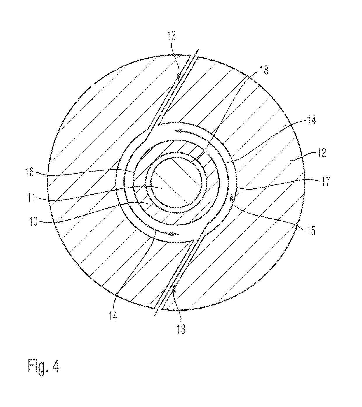
[0008]According to an advantageous embodiment, the or each bore runs at an angle deviating from 90° to the circumferential direction on a boundary wall of the gas space on the housing side. Preferentially, the respective bore includes with the circumferential direction of the boundary wall of the gas space in the region of the bore an angle that is smaller than 80°. Because of this, the gas utilised for heating up or temperature-controlling the dry gas seal is conducted into the gas space formed between the housing and the dry gas seal subject to forming a swirl. This ensures even distribution of the gas in the gas space and thereby effective heating of the dry gas seal within a short time with low required gas quantity.
[0009]According to one aspect of the invention, the or each bore receives a guide tube for the gaseous medium. The gas quantity and time needed for heating up the dry gas seal can be reduced compared with the prior art. The guide tube absorbs less thermal energy than the housing.
[0010]According to one embodiment, a free space is formed between the respective guide tube and a wall of the bore receiving the guide tube. Preferentially, the free space is coupled to the gas space via a bore introduced in the housing or to an interior space of the guide tube via a bore introduced in the guide tube. The free space between the guide tube and the housing provides a thermal insulation for the guide tube, as a result of which heating-up of the dry gas seal can be rendered even more effective.
[0011]According to a further embodiment, the gaseous medium can be directly conducted into the gas space formed between the housing and the dry gas seal via the respective guide tube, wherein preferentially the respective guide tube projects into the gas space compared with a boundary wall of the gas space on the housing side and a section of the respective guide tube projecting into the gas space is bent over in circumferential direction and / or receives a nozzle. Because of this, the gas used for temperature-controlling or heating the dry gas seal can be particularly advantageously introduced into the gas space formed between the housing and the dry gas seal, as a result of which the effectiveness during the heating-up of the dry gas seal can be further increased.

Problems solved by technology

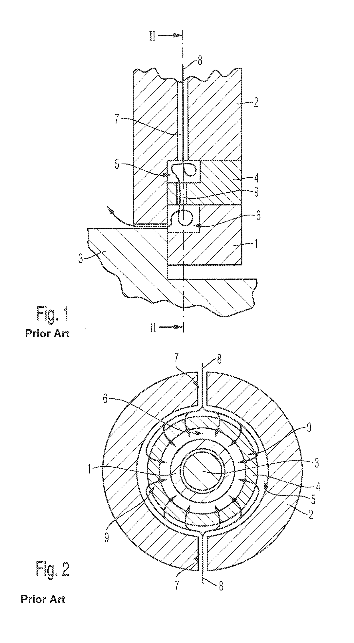
In the case of fluid flow machines known from the prior art, relatively large amounts of gas and a relatively long heating-up time is required for temperature-controlling the dry gas seal 1, namely for heating the same to operating temperature.
This is a disadvantage.

Method used


Image

  • Fluid flow machine using a gaseous medium for temperature control of a dry gas seal
  • Fluid flow machine using a gaseous medium for temperature control of a dry gas seal
  • Fluid flow machine using a gaseous medium for temperature control of a dry gas seal

Examples


Embodiment Construction

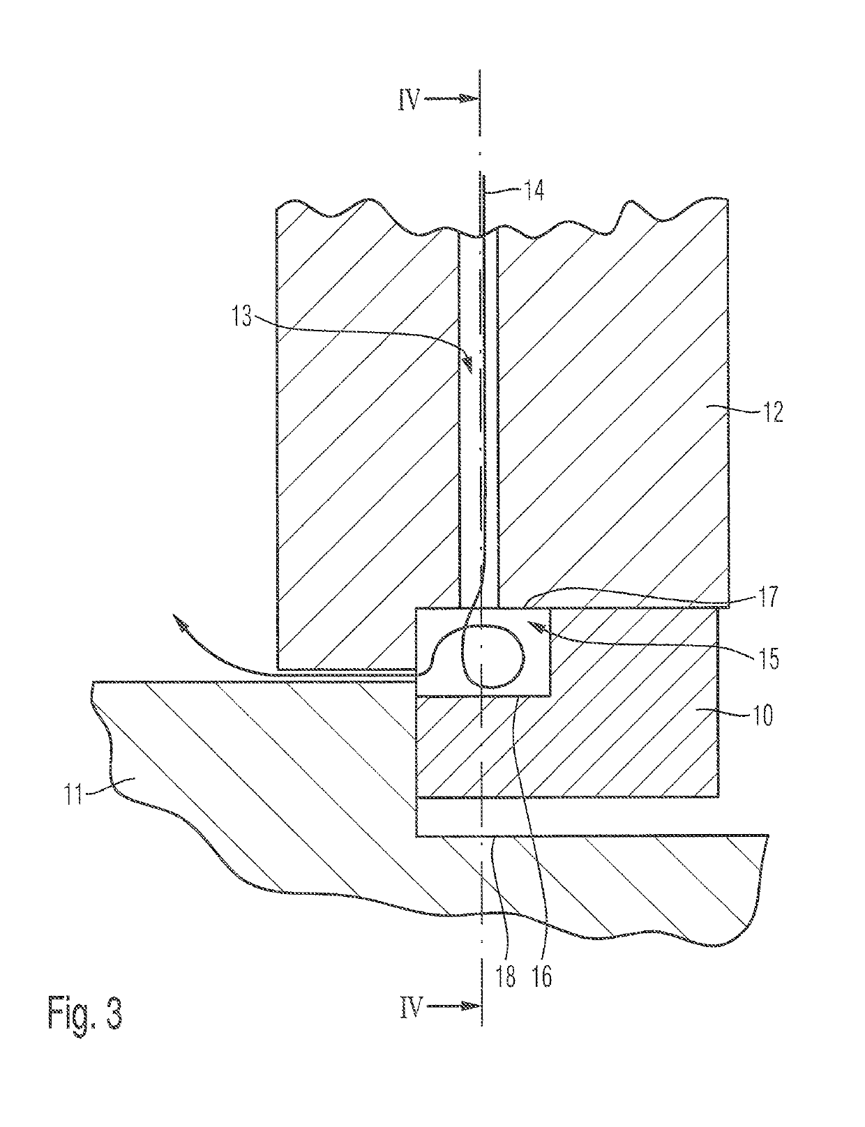
[0021]FIGS. 3 and 4 show a cross section through a fluid flow machine according to one embodiment of the invention in the region of a dry gas seal 10, which is positioned between a rotor 11 and a housing 12 of the fluid flow machine.

[0022]Via at least one recess or bore 13 introduced in the housing 12, gas, which is needed for temperature-controlling or heating the dry gas seal 10, can be conducted in the direction of the dry gas seal 10 in the direction of the arrow 14 via the housing 12.

[0023]According to the first aspect of the present invention, the component positioned according to the prior art between the dry gas seal and the housing, which on the one hand defines a gas space each between the component and the housing and on the other hand between the component and the dry gas seal, is eliminated so that accordingly via the or each bore 13 of the housing 12 the gas can be directly conducted into a gas space 15 formed between the housing 12 and the dry gas seal 10. Accordingly...


PUM


Abstract

A fluid flow machine, in particular turbocompressor, with a housing, having a rotor mounted in the housing, and with a dry gas seal for sealing the rotor relative to the housing. The housing at least one recess or bore for a gaseous medium is introduced, via which the gaseous medium for temperature-controlling the dry gas seal can be conducted in the direction of the same. The gaseous medium can be directly conducted into a gas space formed between the housing and the dry gas seal via the or each recess or bore. Additionally or alternatively, the or each recess or bore receives a guide tube for the gaseous medium.

Description

BACKGROUND OF THE INVENTION[0001]1. Field of the Invention[0002]The present invention relates to a fluid flow machine.[0003]2. Description of the Related Art[0004]The construction of fluid flow machines designed as turbocompressors is known to the person skilled in the art. Accordingly, FIGS. 1 and 2 show different cross sections through a fluid flow machine according to the prior art in the region of a dry gas seal 1, which is positioned between a housing 2 and a rotor 3 of the fluid flow machine. According to the prior art, between the dry gas seal 1 and the housing 2 an annular assembly 4 on the stator side is arranged, wherein on the one hand between this assembly 4 and the housing 2 and on the other hand between this assembly 4 and the dry gas seal 1 a gas space 5 and 6 are formed. At least one bore 7 is introduced into the housing 2 gas. Bore 7 is needed for temperature-controlling the dry gas seal 1 and gas can be initially conducted in the direction of the arrow 8 into the g...

Claims


Application Information

Patent Timeline
Patent Type & Authority Patents(United States)
IPC IPC(8): F01D11/02F01D25/10F01D11/04F04D29/12F04D29/58F16J15/34F01D25/24
CPCF16J15/3404F01D25/10F04D29/584F01D11/04F01D25/24F04D29/122F01D11/02F04D29/124F04D29/12
Inventor MISCHO, BOBMOKULYS, THOMASSCHOLTYSIK, MARTINBIRRER, RETOKLAAS, ANNIKA
Owner MAN ENERGY SOLUTIONS SA
Learn More