Hybrid vehicle

a hybrid vehicle and hybrid technology, applied in the direction of engine-driven generators, gearing details, machines/engines, etc., can solve the problems of difficult to increase the temperature of lubricating oil at a low temperature time, reduce production, and reduce mechanical loss , the effect of high viscosity of lubricating oil

Active Publication Date: 2019-11-05
TOYOTA JIDOSHA KK
View PDF27 Cites 7 Cited by
  • Summary
  • Abstract
  • Description
  • Claims
  • Application Information

AI Technical Summary

Benefits of technology

[0004]Even in the lubricating apparatus, there may be a possibility that a sufficient cooling performance cannot always be secured, and thus a temperature of the rotary machine for travel becomes increased during a high load travel, for example, so that the output is restricted. If an oil cooler is provided to the supply passage of the lubricating oil, cooling performance is improved, but the temperature of the lubricating oil becomes difficult to be increased at a low temperature time. Generally, the lubricating oil has a higher viscosity at the low temperature time, and thus a load of the oil pump and a stirring resistance at lubricated parts become greater, so that mechanical loss due to them causes deterioration of fuel efficiency.
[0005]An object of the disclosure is to properly cool a rotary machine for travel without hindering increase in temperature of lubricating oil at a low temperature time or the like.

Problems solved by technology

Even in the lubricating apparatus, there may be a possibility that a sufficient cooling performance cannot always be secured, and thus a temperature of the rotary machine for travel becomes increased during a high load travel, for example, so that the output is restricted.
If an oil cooler is provided to the supply passage of the lubricating oil, cooling performance is improved, but the temperature of the lubricating oil becomes difficult to be increased at a low temperature time.
Generally, the lubricating oil has a higher viscosity at the low temperature time, and thus a load of the oil pump and a stirring resistance at lubricated parts become greater, so that mechanical loss due to them causes deterioration of fuel efficiency.

Method used


Image

  • Hybrid vehicle
  • Hybrid vehicle
  • Hybrid vehicle

Examples


Embodiment Construction

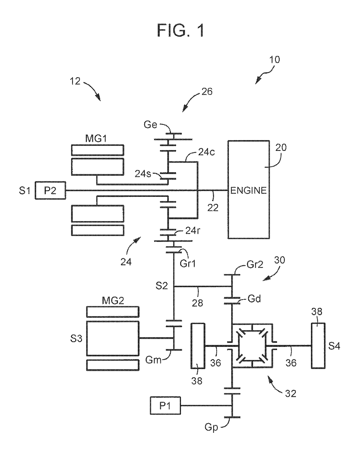
[0030]The present disclosure is preferably applied to a hybrid vehicle including an electric differential unit, but the present disclosure can also be applied to various hybrid vehicles including rotary machines for travel other than engines as drive sources for travel. As the rotary machine for travel, it is proper to use a motor generator that can alternatively use functions of an electric motor and an electric power generator, for example, but an electric motor may also be used. It is also proper to use a motor generator as a rotary machine for differential control of an electric differential unit, but an electric power generator may also be used. By setting a torque of the rotary machine for differential control to be zero, a differential mechanism is allowed to differentially rotate, which prevents the engine from co-rotating.

[0031]An output unit of the power transmission system that drives a first oil pump is a differential device that distributes a drive force transmitted fro...


PUM


Abstract

A hybrid vehicle comprises an engine; a first rotary machine configured to drive the hybrid vehicle; a power transmission system configured to transmit drive force from the engine and the first rotary machine via an output unit to driven wheels; a first oil pump configured to be mechanically rotary-driven along with rotation of the output unit; a second oil pump configured to be rotary-driven by a rotary drive source that is different from the output unit; a first supply passage connected to a discharge side of the first oil pump, and the first supply passage configured to supply lubricating oil at least to the first rotary machine; a second supply passage connected to a discharge side of the second oil pump, and the second supply passage configured to supply lubricating oil at least to the first rotary machine; and an oil cooler provided to the second supply passage.

Description

INCORPORATION BY REFERENCE[0001]The disclosure of Japanese Patent Application No. 2016-159010 filed on Aug. 12, 2016 including the specification, drawings and abstract is incorporated herein by reference in its entirety.BACKGROUND1. Technical Field[0002]The technical field relates to a hybrid vehicle, and particularly to improvement of a lubricating apparatus that is applied to a hybrid vehicle, supplies lubricating oil to a rotary machine for travel, and cools the rotary machine for travel.2. Description of Related Art[0003]There has been proposed a lubricating apparatus applied to (a) a hybrid vehicle including: an engine; a rotary machine for travel; and a power transmission system to transmit a drive force from the engine and rotary machine via an output unit to driven wheels, and the lubricating apparatus includes: (b) a first oil pump mechanically rotary-driven along with rotation of the output unit; (c) a second oil pump rotary-driven by a rotary drive source different from t...

Claims


Application Information

Patent Timeline
Patent Type & Authority Patents(United States)
IPC IPC(8): F01M5/00F01P11/08F16H57/04B60W30/184B60L50/16
CPCF16H57/0441B60W30/1843F16H57/0476F01P11/08F01M5/005F16H57/0415B60K6/22F16H57/0413B60K6/445B60K6/365Y02T10/62B60K6/442B60K11/02B60Y2200/92
Inventor KIYOKAMI, HIROAKINISHIKAWA, YUKINOBUHORI, TETSUOOKUNO, HAKUBA
Owner TOYOTA JIDOSHA KK
Why Eureka
Try Eureka