Thermal management system for fuel cell vehicle

a fuel cell and management system technology, applied in hybrid vehicles, propulsion by batteries/cells, electrochemical generators, etc., can solve the problems of low fuel efficiency and achieve the effect of improving fuel efficiency

Active Publication Date: 2019-11-05
HYUNDAI MOTOR CO LTD +1
View PDF42 Cites 0 Cited by
  • Summary
  • Abstract
  • Description
  • Claims
  • Application Information

AI Technical Summary

Benefits of technology

[0007]Various aspects of the present invention are directed to providing a thermal management system for a fuel cell vehicle that may improve fuel efficiency by continuously supplying heat to a solid-state hydrogen storage container without an additional power supply, and by use of all power generated in a fuel cell for driving the fuel cell vehicle.
[0017]According to the embodiments of the present invention, a separate power supply for supplying heat to the first container is not required, and it is possible to not use power except for operating the auxiliary heater for a short time when an initial chemical reaction is started or when an emergency occurs. Accordingly, the power generated in the fuel cell stack may be fully utilized for driving the vehicle, improving fuel efficiency.
[0018]In addition, since the thermochemical thermal energy storage material with excellent reversibility is utilized, heat loss is small during charging and discharging, and since it is possible to control heat dissipation using the catalyst (H2O or O2), the thermal management system for the fuel cell vehicle according to the exemplary embodiment of the present invention is safe and environmentally friendly. Further, when the catalyst is supplied to the second container without operating the fuel cell stack, since the heating may be performed by the thermal energy emitted from the second container, it is possible to improve energy efficiency.

Problems solved by technology

However, the additional balance of plant (BOP) increases a volume of a related system and causes energy loss, thus it results in low fuel efficiency.

Method used


Image

  • Thermal management system for fuel cell vehicle
  • Thermal management system for fuel cell vehicle
  • Thermal management system for fuel cell vehicle

Examples


Embodiment Construction

[0030]Reference will now be made in detail to various embodiments of the present invention(s), examples of which are illustrated in the accompanying drawings and described below. While the invention(s) will be described in conjunction with exemplary embodiments, it will be understood that the present description is not intended to limit the invention(s) to those exemplary embodiments. On the contrary, the invention(s) is intended to cover not only the exemplary embodiments, but also various alternatives, modifications, equivalents and other embodiments, which may be included within the spirit and scope of the invention as defined by the appended claims.

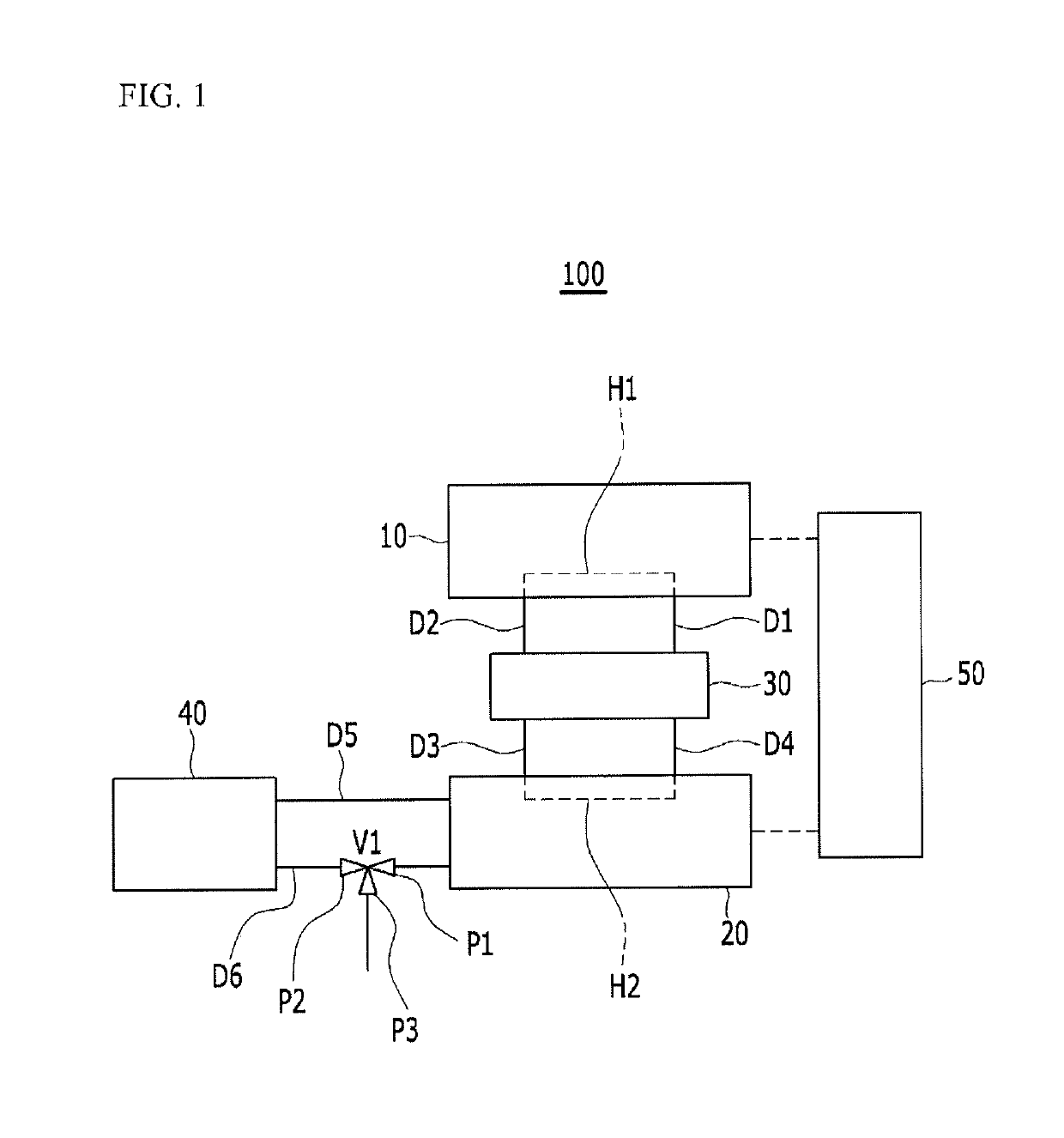
[0031]FIG. 1 illustrates a schematic view of a solid-state hydrogen storage device according to a first exemplary embodiments of the present invention.

[0032]Referring to FIG. 1, a solid-state hydrogen storage device 100 of various exemplary embodiments includes a first container 10 for accommodating a solid-state hydrogen storage mate...


PUM

PropertyMeasurementUnit
heat energyaaaaaaaaaa
volume-storage densityaaaaaaaaaa
heat supply efficiencyaaaaaaaaaa

Abstract

A thermal management system for a fuel cell vehicle may include a fuel cell stack, a solid-state hydrogen storage device, and a hydrogen supply pipe, wherein the fuel cell stack receives hydrogen and air configured to generate electricity and discharge water, wherein the solid-state hydrogen storage device includes a first container accommodating a solid-state hydrogen storage material, a second container accommodating a thermochemical thermal energy storage material, a third container accommodating a heat transfer medium, and pipes connected to the first container, the second container, and the third container to circulate the heat transfer medium, and wherein the hydrogen supply pipe is connected to the first container and the fuel cell stack.

Description

CROSS-REFERENCE TO RELATED APPLICATION[0001]The present application claims priority to Korean Patent Application No. 10-2017-0020669 filed on Feb. 15, 2017, the entire contents of which are incorporated herein for all purposes by this reference.BACKGROUND OF THE INVENTIONField of the Invention[0002]The present invention relates to a thermal management system for a fuel cell vehicle.Description of Related Art[0003]A hydrogen fuel cell is an environmentally-friendly power generation device that generates electricity by supplying hydrogen and air and discharges pure water, and may be utilized as a power source for an electric vehicle. The hydrogen fuel cell may receive hydrogen from a solid-state hydrogen storage container. The solid-state hydrogen storage container includes a hydrogen storage material that discharges hydrogen at a specific temperature, and a complex hydride based on a metal hydride may be used as the hydrogen storage material to increase volume-storage density.[0004]T...

Claims


Application Information

Patent Timeline
Patent Type & Authority Patents(United States)
IPC IPC(8): C01B3/00H01M8/04007H01M8/04082H01M8/04701H01M8/0432H01M8/065H01M8/04291
CPCH01M8/04037H01M8/04074H01M8/04216H01M8/04335H01M8/065H01M8/04291H01M8/04052H01M8/0432H01M8/04708H01M8/04373Y02T90/34Y02T10/7005H01M2250/20Y02T90/32H01M8/2457H01M8/04014H01M8/04029Y02T90/40Y02E60/50Y02T10/70Y02T10/7072Y02T90/12B60L50/71B60L53/54Y10S903/908
Inventor JANG, JUNHONAM, DONG HOON
Owner HYUNDAI MOTOR CO LTD
Why Eureka
Try Eureka