Rotary compressor having fluid passage between sliding vane and vane slot

Active Publication Date: 2019-11-12
LG ELECTRONICS INC
View PDF10 Cites 2 Cited by
  • Summary
  • Abstract
  • Description
  • Claims
  • Application Information

AI Technical Summary

Benefits of technology

This patent is about a new compressor that can reduce friction between the roller and vane, which helps improve efficiency. It also allows for control of the contact force between the vane and roller based on the size of the vane's protrusions. Additionally, it prevents the vane from being released during certain parts of the compressor's operation.

Problems solved by technology

Accordingly, the former case has a disadvantage in which a plurality of cylinders may be provided in an axial direction, thereby increasing a size of the compressor to that extent as well as increasing the material cost.
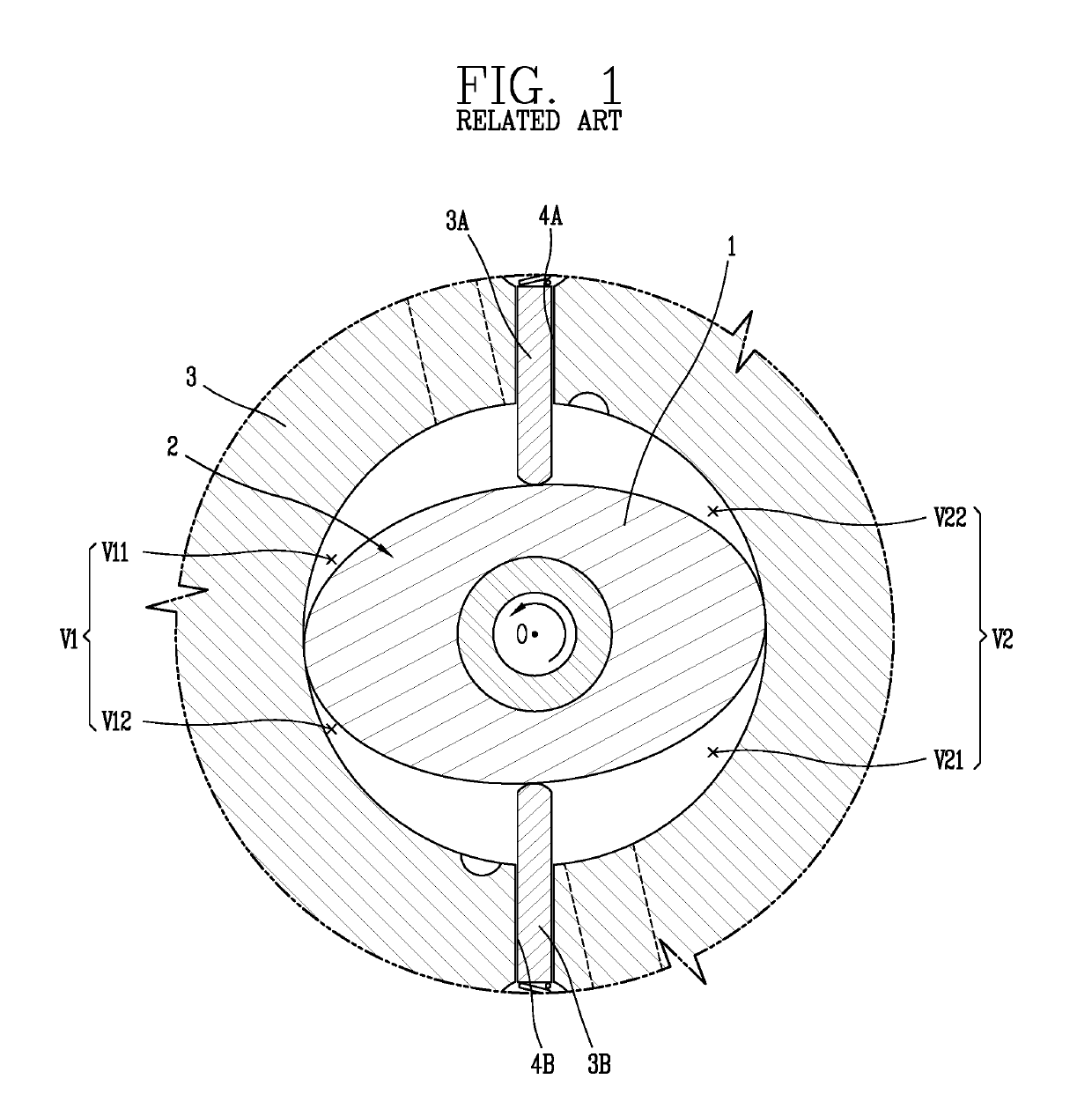
However, the foregoing rotary compressor in the related art may have a problem of an overpressure loss due to a short compression period and a machine loss increase due to no roller rotation.
According to the mechanical friction loss generated between the roller 2 and the vanes (3A)(3B), a linear velocity proportionally may increase as increasing a number of vanes in the same inner diameter and height condition of the cylinder, thereby significantly reducing the compressor efficiency.
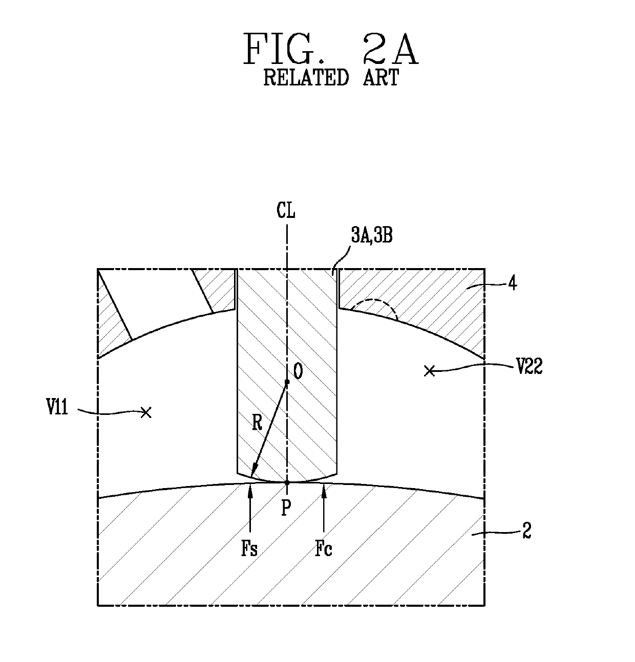
Furthermore, according to the rotary compressor in the related art, an front end of the vanes (3A)(3B) may be brought into contact with an outer circumferential surface of the roller 2 rotating without rotation to increase a mechanical friction loss between the roller 2 and the vanes (3A)(3B), but if a back pressure to each of the vanes (3A)(3B) is too reduced in consideration of this, it may cause a problem in which refrigerant is leaked into the suction chamber while decreasing a contact force between the vanes (3A)(3B) and the roller 2.
Furthermore, the rotary compressor in the related art has a problem in which a release point at which the roller 2 is separated from the vanes (3A)(3B) may occur according to a rotation angle of the roller 2, and in particular, in case where the roller 2 is in an oval shape, a variation amount of a contact point between the vanes (3A)(3B) and the roller 2 increases, and due to this, an area of generating a release point between the vanes (3A)(3B) and the roller 2 also increases to limit the design freedom of the compressor.
It also has a problem in which a gas force that can be received by an end portion of the vane (3A) is limited to increase a mechanical friction loss generated between the vane and the roller.
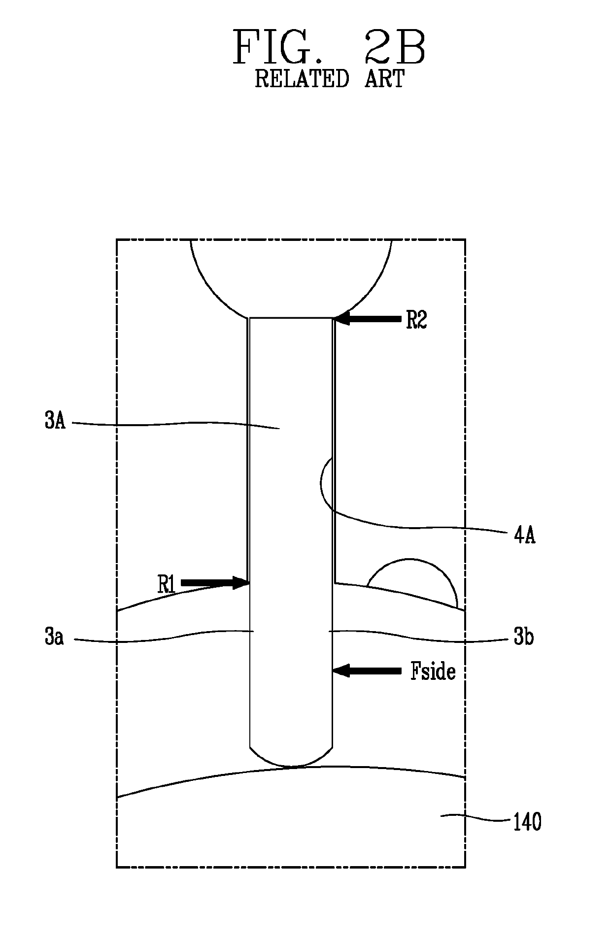
Accordingly, the reaction forces (R1)(R2) applied to both side surfaces of the vane significantly may increase, thereby causing a problem of increasing a mechanical friction loss between the vane and the cylinder while the vane (3A) and the vane slot (4A) are excessively adhered to each other.
Furthermore, according to the rotary compressor in the related art, as the vanes (3A)(3B) receive a larger side directional gas force (Fside) in a suction chamber direction due to a pressure of the compression chamber in which the vanes (3A)(3B) have a relatively high pressure, a gap between the roller and the vane may be generated, thereby causing a problem in which refrigerant is leaked while a contact force between the roller and the vane excessively decreases.
It may increase an area of the vane exposed to the compression chamber while increasing a maximum protrusion amount of the vanes (3A)(3B) in case of an oval shaped roller 2, and due to this, a side directional gas force (Fside) receiving at the compression chamber by the vane may further increase, thereby causing a problem of increasing refrigerant leakage.

Method used


Image

  • Rotary compressor having fluid passage between sliding vane and vane slot
  • Rotary compressor having fluid passage between sliding vane and vane slot
  • Rotary compressor having fluid passage between sliding vane and vane slot

Examples


Embodiment Construction

[0099]Hereinafter, a compressor according to present disclosure will be described in detail based on an embodiment illustrated in the accompanying drawings.

[0100]FIG. 3 is a longitudinal cross-sectional view illustrating an oval shaped rotary compressor according to the present disclosure, and FIG. 4 is an exploded perspective view illustrating a compression section in the compressor according to FIG. 3, and FIG. 5 is a transverse directional view illustrating a compression section in the compressor according to FIG. 3.

[0101]As illustrated in the drawings, in a rotary compressor according to the present embodiment, a motor drive 20 is provided within a casing 10, and a compression section 100 mechanically connected by a rotating shaft 30 may be provided at a lower side of the motor drive 20.

[0102]The casing 10 may include a cylindrical shell 11, an upper shell 12 configured to cover an upper portion of the cylindrical shell 11, and a lower shell 13 configured to cover a lower portio...


PUM


Abstract

A compressor is provided in which an outer circumferential side cross-sectional area of a vane slot is formed smaller than an inner circumferential side cross-sectional area thereof to decrease an area receiving a force in a roller direction by a vane to reduce a contact force between the roller and the vane, and a gas accommodation portion selectively forming a suction pressure and an intermediate pressure is formed between the vane and the vane slot to control the contact force. A contact surface of the vane facing the roller is formed at a side of a compression chamber to reduce the contact force, and a space forming a discharge pressure is formed at at least either one side of a side surface of the vane and a cylinder to decrease a side directional reaction force applied to the vane, thereby reducing a friction between the vane and the cylinder.

Description

CROSS-REFERENCE TO RELATED APPLICATIONS[0001]The present disclosure relates to subject matter contained in priority Korean Application Nos. 10-2016-0013067 and 10-2016-0013071, filed on Feb. 2, 2016, which are herein expressly incorporated by reference in their entirety.BACKGROUND OF THE INVENTION1. Field of the Invention[0002]The present disclosure relates to a compressor, and more particularly, to a rotary compressor divided into a suction chamber and a compression chamber by a vane being brought into contact with a rotating roller.2. Description of the Related Art[0003]In general, compressors may be divided into a rotating type and a reciprocating type according to a method of compressing refrigerant. The rotating type compressor varies a volume of a compression chamber while a piston performs a rotational or orbiting movement in a cylinder, and the reciprocating type compressor varies a volume of a compression space while a piston performs a reciprocal movement in a cylinder. A ...

Claims


Application Information

Patent Timeline
IPC IPC(8): F04C18/356F01C21/08F04C27/00F04C29/00F04C23/00
CPCF04C27/005F04C29/0085F04C18/3566F04C18/3568F01C21/0809F04C2240/20F04C2240/60F04C23/008F04C2240/30F04C2240/10F01C21/0827
Inventor LEE, YUNHIKANG, SEOUNGMINSHIN, JINUNGMOON, SEOKHWANLEE, BYEONGCHUL
Owner LG ELECTRONICS INC
Why Eureka
Try Eureka