
Additive manufacturing using a selective recoater

a recoater and additive manufacturing technology, applied in the direction of manufacturing tools, soldering devices, auxilary welding devices, etc., can solve the problems of complex process, limited parts being built in this type of apparatus, and the effects of processing parameters on the microstructural evolution of the layer manufacturing process,

Active Publication Date: 2019-11-19
GENERAL ELECTRIC CO
View PDF79 Cites 76 Cited by
  • Summary
  • Abstract
  • Description
  • Claims
  • Application Information

AI Technical Summary

Benefits of technology

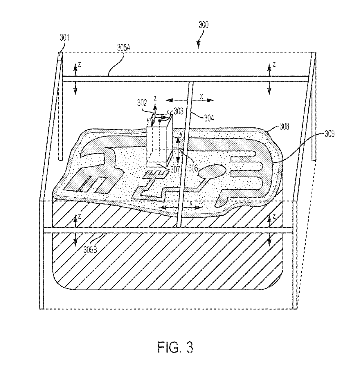
The present invention has the advantage that it allows for the formation of large parts with a small angle beam. The build unit can be moved to a new location to create new parts of the object being formed. The energy beam creates a circular scan area around its center point, which is defined by the point on the powder where it touches when the beam is at a certain angle. This scan area is smaller than the smallest cross-sectional area of the object being formed. There is no upper limit on the size of the object.

Problems solved by technology

Although the laser sintering and melting processes can be applied to a broad range of powder materials, the scientific and technical aspects of the production route, for example, sintering or melting rate and the effects of processing parameters on the microstructural evolution during the layer manufacturing process have not been well understood.
This method of fabrication is accompanied by multiple modes of heat, mass and momentum transfer, and chemical reactions that make the process very complex.
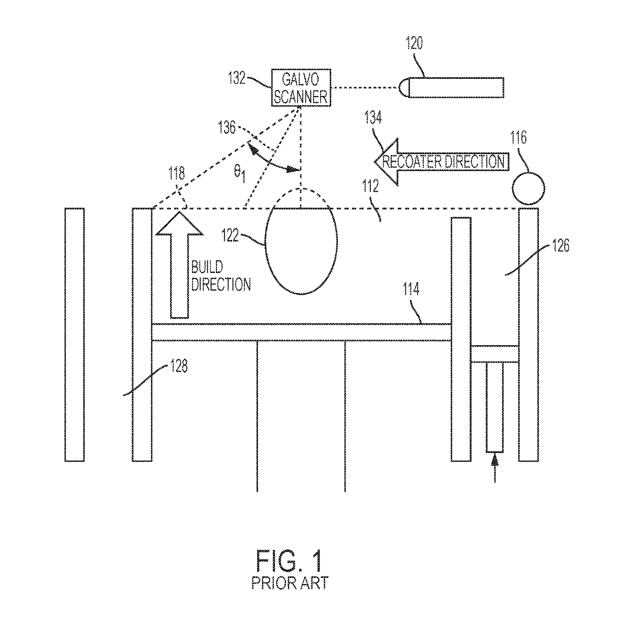
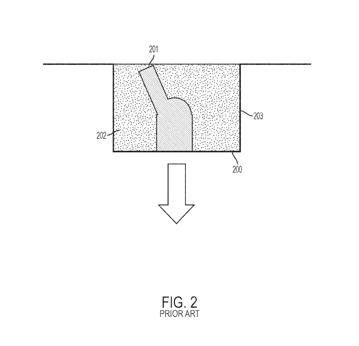
The weight of the powder within the build environment is one limitation on the size of parts being built in this type of apparatus.
The amount of powder needed to make a large part may exceed the limits of the build platform 114 or make it difficult to control the lowering of the build platform by precise steps which is needed to make highly uniform additive layers in the object being built.
These melt pool differences may result in defects and loss of fidelity in these regions of the part being built.
These defects may result in inferior surface finishes on the desired part.
Another problem that arises with prior art methods and systems involves cooling the layer of powdered material and removing smoke, condensates, and other impurities produced by irradiating the powder (sometimes called the “gas plume”), which can contaminate the object and obscure the line of sight of the energy beam.
For large objects, i.e. objects with a largest dimension in the xy plane (for conventional powder bed systems, the plane of the powder bed) of 400 to 450 mm, it is very difficult to provide consistent laminar gas flow and efficient removal of unwanted gasses, particulates, condensates, and other undesirable impurities and contaminants.
Another problem that arises in the prior art systems and methods is the need to finely control the quantity and location of powder deposited to avoid wasting powder, while also avoiding contact of the powder with undesirable materials.
These mechanisms utilize multiple moving parts that may malfunction, or may be made of materials that are not suited to contact with the powder due to concerns with contamination.
Such an apparatus is more prone to failure, because the rotating conveyor shafts must be in motion as long as powder is being deposited.
Other attempts to overcome the limitations of conventional powder bed systems have failed to address the problems associated with scale-up of these machines.
In some cases, attempts to provide large format systems have introduced additional problems and challenges in creating laser fused parts from powder.
Prior systems failed to provide uniform layer-wise powder distribution, effective management of the gas plume, and good control of the laser energy density over the part being produced.
Because there is no discussion of how to achieve uniform layers or powder over the part being built, the dimensional accuracy of such systems are very limited.
Moreover, because the build environment is large, achieving a suitable gas environment near the laser melt pool would be difficult.
For large objects, it is difficult to build a platform that can both stably hold sufficient powder, and also be lowered by the precise layer thickness required.

Method used


Image

  • Additive manufacturing using a selective recoater
  • Additive manufacturing using a selective recoater
  • Additive manufacturing using a selective recoater

Examples


Embodiment Construction

[0045]This detailed description and accompanying figures demonstrate some illustrative embodiments of the invention to aid in understanding. The invention is not limited to the embodiments illustrated in the figures, nor is it limited to the particular embodiments described herein.

[0046]The present invention relates to an apparatus that can be used to perform additive manufacturing, as well as methods for utilizing the apparatus to additively manufacture objects. The apparatus includes components that make it particularly useful for making large additively manufactured objects. One aspect of the present invention is a build unit. The build unit may be configured to include several components necessary for making high precision, large scale additively manufactured objects. These components may include, for example, a recoater, a gasflow device with a gasflow zone, and an irradiation emission directing device. An irradiation emission directing device used in an embodiment of the prese...


PUM

PropertyMeasurementUnit
scan speedsaaaaaaaaaa
angleaaaaaaaaaa
widthaaaaaaaaaa

Abstract

The present disclosure generally relates to additive manufacturing systems and methods on a large-scale format. One aspect involves a build unit that can be moved around in three dimensions by a positioning system, building separate portions of a large object. The build unit has an energy directing device that directs, e.g., laser or e-beam irradiation onto a powder layer. In the case of laser irradiation, the build volume may have a gasflow device that provides laminar gas flow to a laminar flow zone above the layer of powder. This allows for efficient removal of the smoke, condensates, and other impurities produced by irradiating the powder (the “gas plume”) without excessively disturbing the powder layer. The build unit may also have a recoater that allows it to selectively deposit particular quantities of powder in specific locations over a work surface to build large, high quality, high precision objects.

Description

[0001]The present disclosure generally relates to methods and systems adapted to perform additive manufacturing (“AM”) processes, for example by direct melt laser manufacturing (“DMLM”), on a larger scale format.CROSS REFERENCE TO RELATED APPLICATIONS[0002]Reference is made to the following related applications filed concurrently, the entirety of which are incorporated herein by reference:[0003]U.S. patent application Ser. No. 15 / 406,467, titled “Additive Manufacturing Using a Mobile Build Volume,” and filed Jan. 13, 2017.[0004]U.S. patent application Ser. No. 15 / 406,454, titled “Additive Manufacturing Using a Dynamically Grown Build Envelope,” and filed Jan. 13, 2017.[0005]U.S. patent application Ser. No. 15 / 406,454, titled “Additive Manufacturing Using a Dynamically Grown Wall,” and filed Jan. 13, 2017.[0006]U.S. patent application Ser. No. 15 / 406,471, titled “Large Scale Additive Machine,” and filed Jan. 13, 2017.BACKGROUND[0007]A description of a typical laser powder bed fusion ...

Claims


Application Information

Patent Timeline
Patent Type & Authority Patents(United States)
IPC IPC(8): B22F3/10B33Y50/02B33Y40/00B23K15/00B23K26/342B23K26/14B23K26/08B23K37/02B33Y30/00B22F3/105B33Y10/00
CPCB23K26/1437B23K37/0235B23K26/0876B33Y10/00B23K15/0086B33Y40/00B23K26/342B23K15/002B33Y50/02B33Y30/00B22F3/1055B22F2003/1056B29C64/329B29C64/205Y02P10/25B22F10/28B22F12/44B22F12/49B22F12/52B22F10/40B22F10/322B22F12/67B22F12/90B22F12/70
Inventor REDDING, MACKENZIE RYANFIELDMAN, ZACHARY DAVIDMAMRAK, JUSTIN
Owner GENERAL ELECTRIC CO
Learn More