Light fixture and lens for a light fixture

a technology of light fixture and lens, which is applied in the direction of fixed installation, lighting and heating equipment, instruments, etc., can solve the problems of low optical efficiency, low emission angle, and difficult to achieve the illumination of a complete room with such low emission angle, and achieve the effect of improving optical efficiency

Active Publication Date: 2019-11-19
LEDVANCE GMBH
View PDF8 Cites 5 Cited by
  • Summary
  • Abstract
  • Description
  • Claims
  • Application Information

AI Technical Summary

Benefits of technology

[0006]Starting from the background described above, it is an object of the present invention to provide a light fixture with an emission angle in the range from 50° to 80° and an improved optical efficiency. A further object of the invention is to provide a lens for such a light fixture.
[0009]The invention is based, in particular, on the idea of providing an already existing housing for a light fixture with a lens which reduces the emission angle of the light-emitting diode to a value of at least 50° and at most 80°. The lens is preferably configured as a convergent lens. The dimensions of the lens can be adapted to the dimensions of the housing, in particular of the depression thereof. Mounting components and / or protrusions for example, which project out of the mounting surface of the light-emitting diode in the vertical direction, in particular at least 1 mm, can be received in the depression of the housing. Preferably such components projecting out of the mounting surface should not come into contact with the lens in order to avoid damage to the lens. On the other hand, the lens should have the least possible spacing from the light-emitting diode in order to limit light losses.
[0029]According to at least one embodiment of the light fixture the lens, in particular, the focus area of the lens has precisely two annular Fresnel steps. In this case the lens, in particular the focus area thereof, preferably has one single central lens area. The higher the number of Fresnel steps the thicker the lens and, in particular, the focus area thereof can be reduced. Conversely the efficiency of the lens decreases as the number of Fresnel steps increases. Particularly, this is because the Fresnel steps do not have an ideal pointed shape due to their production but can be rounded. A compromise between the two said effects can be achieved by the choice of two Fresnel steps. In particular, the number of Fresnel steps is selected so that a compromise between high efficiency and lesser complexity, for example for easier producibility, as well as optimal overall height of the lens is achieved.
[0033]According to at least one embodiment of the light fixture, the cavity and / or the cavity step is / are designed and arranged in such a way that a part of the light emitted by the light-emitting diode in operation of the light fixture impinges on the cavity step, in particular the cavity inner face thereof, and is at least partially deflected by means of total reflection on the cavity inner face and / or the cavity outer face of the cavity step. Thus, the cavity step has characteristics of a total internal reflection (TIR) lens. The totally reflected light is preferably deflected forwards, so that it leaves the lens surface outside the refractive part of the lens, in particular outside the refractive Fresnel steps. A light fixture having a high optical efficiency can be provided by the combination of the refractive Fresnel elements and the totally reflecting cavity step.
[0034]According to at least one embodiment of the light fixture, a light exit surface of the lens facing away from the light-emitting diode is roughened at least at some points, preferably completely. A blending of light of different colors in the lens can be improved by means of such roughening. This is advantageous, in particular, when the light-emitting diode comprises a light-emitting diode chip which emits blue and a conversion element which converts the blue light emitted by the light-emitting diode chip emitted into differently colored light, in particular yellow, green and / or red light. The different color components of the light emitted by the light-emitting diode are then preferably mixed in the lens. This mixing can be improved by means of a roughening on the light exit surface, wherein it is possible that the efficiency of the light fixture is reduced as a result.

Problems solved by technology

This enables efficient illumination of individual regions in the room, but illumination of a complete room with such low emission angles can only be achieved with difficulty.
However, only relatively little light is emitted downwards, where the light is most required for illumination.
However, already existing optical units, with which such an emission angle can be produced, have a low optical efficiency.
However, in the design of an optical unit, the spatial dimensions for improvement of the optical efficiency cannot be selected arbitrarily.

Method used


Image

  • Light fixture and lens for a light fixture
  • Light fixture and lens for a light fixture
  • Light fixture and lens for a light fixture

Examples


Embodiment Construction

[0041]The light fixtures described here, as well as the lens described here, are explained in greater detail below with reference to exemplary embodiments and the associated drawings. In this case elements which are the same, of the same kind, similar or equivalent are provided with the same reference numerals. Repeated description of some of these elements is omitted in order to avoid redundancies.

[0042]The drawings and the size ratios of the elements illustrated in the drawings elements should not be regarded as drawn to scale relative to one another. On the contrary, individual elements may be shown as excessively large for better illustration and / or to aid understanding.

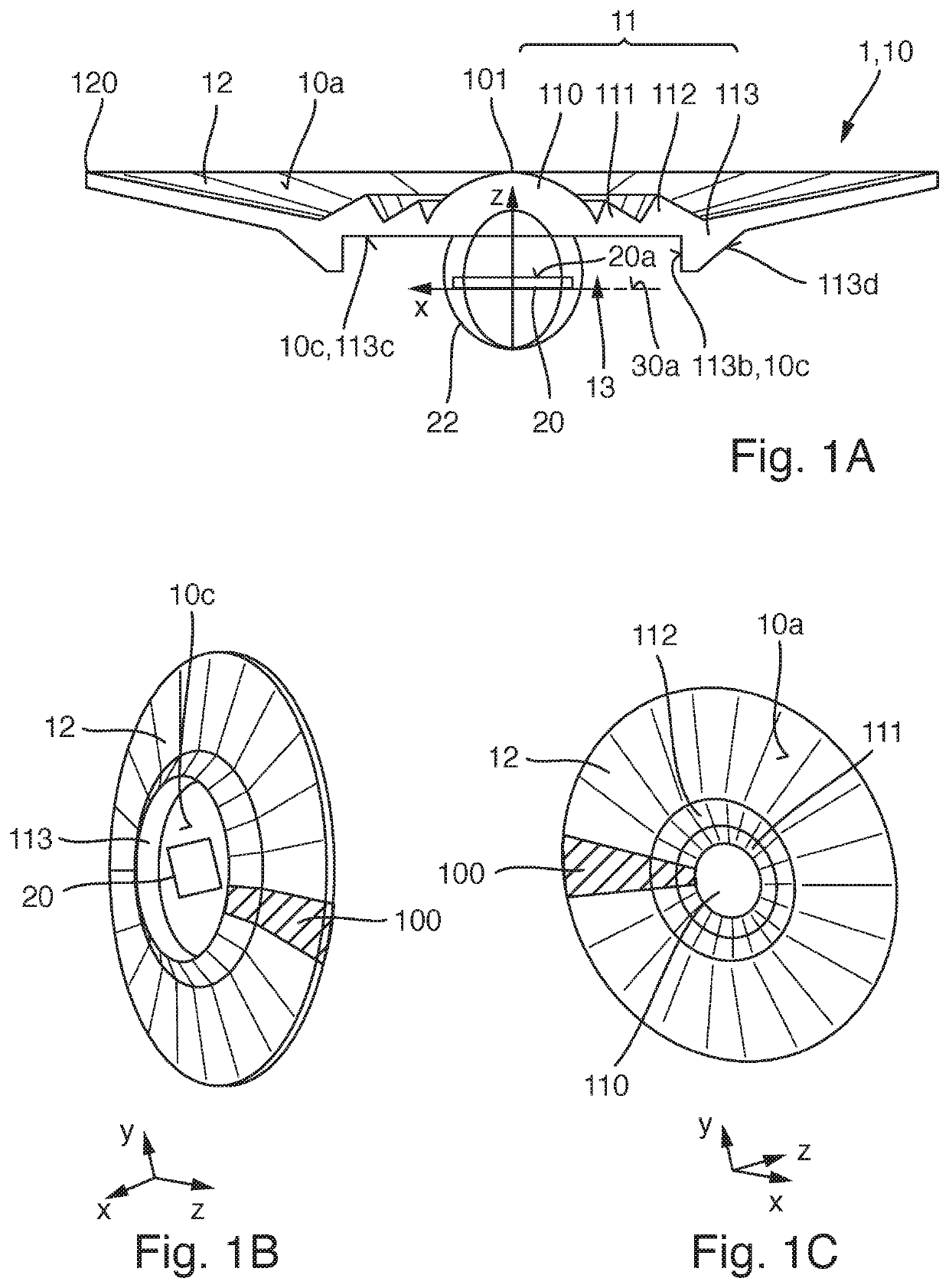
[0043]An exemplary embodiment of a lens 10 described here as well as a light fixture 1 described here is explained in greater detail with reference to the schematic sectional view of FIG. 1A and the schematic plan views of FIGS. 1B and 10. The housing 30 of the light fixture 1 is not shown in FIGS. 1A to 1C.

[0044...


PUM


Abstract

A light fixture has a housing having a depression in which at least one light-emitting diode is received. The light-emitting diode is mounted on a mounting surface and in operation of the light fixture emits light with an initial emission angle of more than 80°. A lens is arranged downstream of the light-emitting diode, having a central focus area and an outer area radially surrounding the focus area. The central focus area is configured and / or arranged in such a way that a part of the light propagating through the focus area is focused in such a way that a final emission angle of the light propagated through the focus area is at least 50° and at most 80°. The outer area of the lens is spaced at least 2 mm from the mounting surface in a vertical direction.

Description

CROSS-REFERENCE TO RELATED APPLICATIONS AND PRIORITY[0001]This patent application claims priority from German Patent Application No. 102017116885.0 filed Jul. 26, 2017, which is herein incorporated by reference in its entirety.TECHNICAL FIELD[0002]The present invention relates to a light fixture as well as a lens for a light fixture.TECHNICAL BACKGROUND[0003]Because of their high energy efficiency, light fixtures with light-emitting diodes as light source (so-called LED retrofit lamps) are growing in popularity as a replacement for conventional light fixtures such as halogen or incandescent lamps. In contrast to conventional light fixtures, however, the light generated by light-emitting diodes usually does not cover the entire solid angle homogeneously. However, the generated radiation profile can be adapted by suitable optical units. As a result, in particular, LED spot lights can be provided which emit at a defined and in particular relatively narrow emission angle.[0004]Currently...

Claims


Application Information

Patent Timeline
Patent Type & Authority Patents(United States)
IPC IPC(8): F21K9/65F21K9/69F21V5/04F21K9/237G02B19/00F21Y115/10
CPCF21K9/65F21V5/045F21K9/237G02B19/00F21K9/69F21Y2115/10F21S8/00F21V5/04G02B19/0061
Inventor STREPPEL, HENRIKE
Owner LEDVANCE GMBH
Why Eureka
Try Eureka