Ablation device with optimized input power profile and method of using the same

a power profile and implantable technology, applied in the field of medical procedures, can solve the problems of untargeted collateral tissue necrosis, scars extending along the path, and all the risks and expenses associated with cardiac surgery

Active Publication Date: 2019-12-10
RECOR MEDICAL INC
View PDF562 Cites 8 Cited by
  • Summary
  • Abstract
  • Description
  • Claims
  • Application Information

AI Technical Summary

Problems solved by technology

This results in formation of a scar extending along the path where tissue damage occurred.
Such a scar can be created by conventional surgery, but this entails all of the risks and expense associated with cardiac surgery.
However, with the conventional methods and apparatus, the collateral tissue immediately adjacent to the intended ablation target can heat up to a temperature that may result in unwanted necrosis of untargeted collateral tissue.
This unwanted necrosis of collateral tissue results from excess temperature elevation, in the targeted tissue.
If the amount of heat energy is sufficiently high, than heat conducted from the targeted tissue to the collateral tissue results in elevated collateral tissue temperature sufficient to create unwanted necrosis.
Thus, there remains an unmet need for an optimized power delivery profile that quickly elevates the targeted tissue to temperatures resulting in necrosis, then maintains that temperature at a constant or near constant level for a period of time needed to achieve complete targeted tissue necrosis while, at the same time, ensures that heat conducted to adjacent collateral structures remain insufficient to cause unwanted or untargeted necrosis.

Method used


Image

  • Ablation device with optimized input power profile and method of using the same
  • Ablation device with optimized input power profile and method of using the same
  • Ablation device with optimized input power profile and method of using the same

Examples


Embodiment Construction

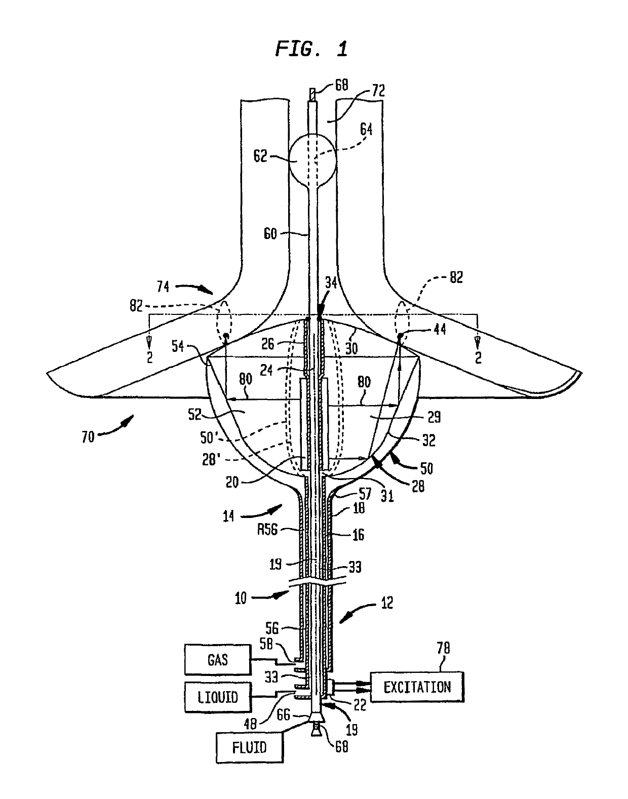
[0019]FIG. 1 shows one embodiment of ablation device of the invention. Many more embodiments of ablation device are disclosed in commonly assigned U.S. Pat. No. 6,635,054. Each of these embodiments can be used with the invention described herein. A portion of a probe structure 10 between proximal and distal ends 12 and 14 respectively is omitted in FIG. 1 for clarity of illustration. The probe structure includes a tubular first catheter 16 and a tubular second catheter 18 surrounding first catheter 16.

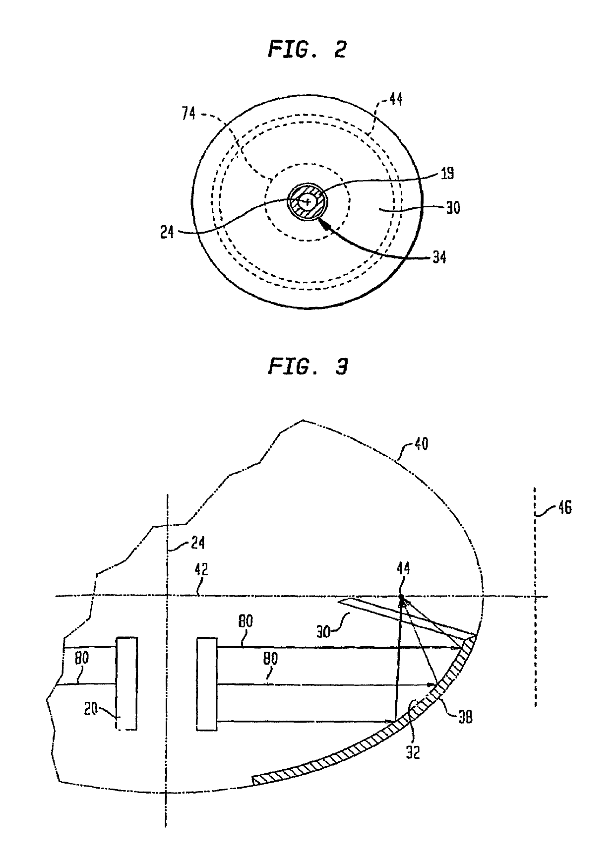
[0020]First catheter 16 and a cylindrical transducer 20 define a central axis 24 adjacent the distal end of the probe structure. First catheter 16 has a distal tip 26 projecting distally beyond transducer 20. A first balloon 28, also referred to herein as a “structural balloon,” is mounted to first catheter 16 at the distal end thereof. First balloon 28 includes an active wall 32 formed from film which is flexible but which can form a substantially noncompliant balloon structure when i...


PUM


Abstract

Ablation device including a probe structure 10 having a proximal end 12 and a distal end 14. Probe structure 10 includes a tubular first catheter 16, a tubular second catheter 18 surrounding the first catheter and a tubular guide catheter extending within the first catheter 16. The first catheter 16 carries a cylindrical ultrasonic transducer 20 adjacent its distal end. The transducer 20 is connected to a source of electrical excitation. The ultrasonic waves emitted by the transducer are directed at the heart wall tissue. Once the tissue reaches the target temperature, the electrical excitation is turned on and off to maintain the tissue at the target temperature. Alternatively, the transducer 20 is subjected to continuous excitation at one power level and upon the tissue reaching the target temperature, the power level of the continuous excitation is switched to a second lower power level.

Description

CROSS REFERENCE TO RELATED APPLICATIONS[0001]The present application claims benefit of U.S. Provisional Application No. 60 / 802,243, filed May 19, 2006, the disclosure of which is hereby incorporated by reference herein.FIELD OF THE INVENTION[0002]The present invention relates to medical procedures such as ablation and to apparatus and method for carrying out such procedures.BACKGROUND OF THE INVENTION[0003]Ultrasonic heating such as high intensity focused ultrasound (HIFU) is utilized for certain therapeutic applications. As disclosed in commonly assigned International Application PCT / US98 / 1062, published as International Publication WO / 98 / 52465 the disclosure of which is hereby incorporated by reference herein, HIFU heating typically is conducted using an ultrasonic emitter having an array of transducers. The transducers are actuated with a drive signal so as to emit ultrasonic waves. The relative phasing of the waves is controlled by the physical configuration of the array and the...

Claims


Application Information

Patent Timeline
Patent Type & Authority Patents(United States)
IPC IPC(8): A61B17/22
CPCA61B17/2202A61B2017/22024A61B2017/22051A61B18/082A61B18/1492A61B2018/00244A61B2018/00351A61B2018/00702A61B2018/00714
Inventor WARNKING, REINHARD
Owner RECOR MEDICAL INC
Why Eureka
Try Eureka