Evaporator

a technology of evaporator and evaporator body, which is applied in the direction of indirect heat exchangers, safety devices for heat exchange apparatus, lighting and heating apparatus, etc., can solve the problems of evaporator becoming costly and evaporator becoming heavier, and achieve the reduction of weight and evaporator cost, the effect of limiting the generation of the noise that reaches the vehicle compartmen

Active Publication Date: 2019-12-10
DENSO CORP
View PDF41 Cites 0 Cited by
  • Summary
  • Abstract
  • Description
  • Claims
  • Application Information

AI Technical Summary

Benefits of technology

[0007]When a generation of noise is limited by attaching a component having a large relative density to the evaporator, the evaporator may become heavier. Moreover, since the unvulcanized butyl rubber that is used as the vibration suppression layer is a relatively expensive material, the evaporator may become costly.
[0008]It is an objective of the present disclosure to provide an evaporator capable of limiting a generation of a noise transferred to a driver's seat of a vehicle without increasing the weight and the cost of the evaporator.
[0015]As described above, according to the evaporator of the present disclosure, the transfer of the vibration through the holding portion of the air conditioning system can be limited while the vibration of the evaporator is not limited. Accordingly, a generation of a noise that reaches a driver's seat of a vehicle is limited. The packing can be made without using a material whose weight and cost are large such as unvulcanized butyl rubber.
[0016]According to the present disclosure, a weight and a cost of the evaporator can be reduced, and the generation of the noise that reaches the vehicle compartment can be limited.

Problems solved by technology

When a generation of noise is limited by attaching a component having a large relative density to the evaporator, the evaporator may become heavier.
Moreover, since the unvulcanized butyl rubber that is used as the vibration suppression layer is a relatively expensive material, the evaporator may become costly.

Method used


Image

  • Evaporator
  • Evaporator
  • Evaporator

Examples


Embodiment Construction

[0023]Hereinafter, an embodiment for implementing the present disclosure will be described referring to drawings. In the respective drawings, a part that corresponds to a matter illustrated in a preceding drawing may be assigned the same reference numeral, and redundant explanation for the part may be omitted.

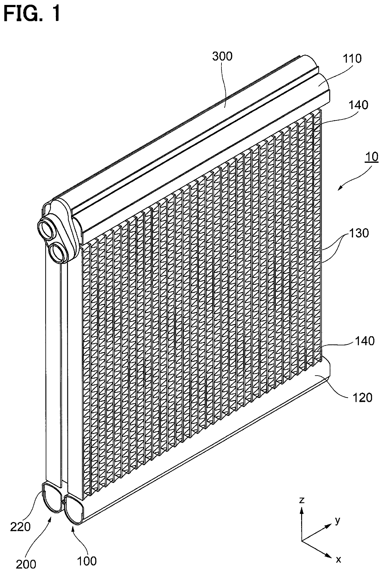
[0024]An evaporator 10 shown in FIG. 1 constitutes a part of a refrigeration cycle that is an air conditioning system for a vehicle. A refrigerant is sent to the evaporator 10 from a radiator located upstream of the evaporator in the refrigeration cycle. The refrigerant sent into the evaporator 10 is evaporated, and the evaporator 10 performs a heat exchange between the refrigerant and an air to cool the air.

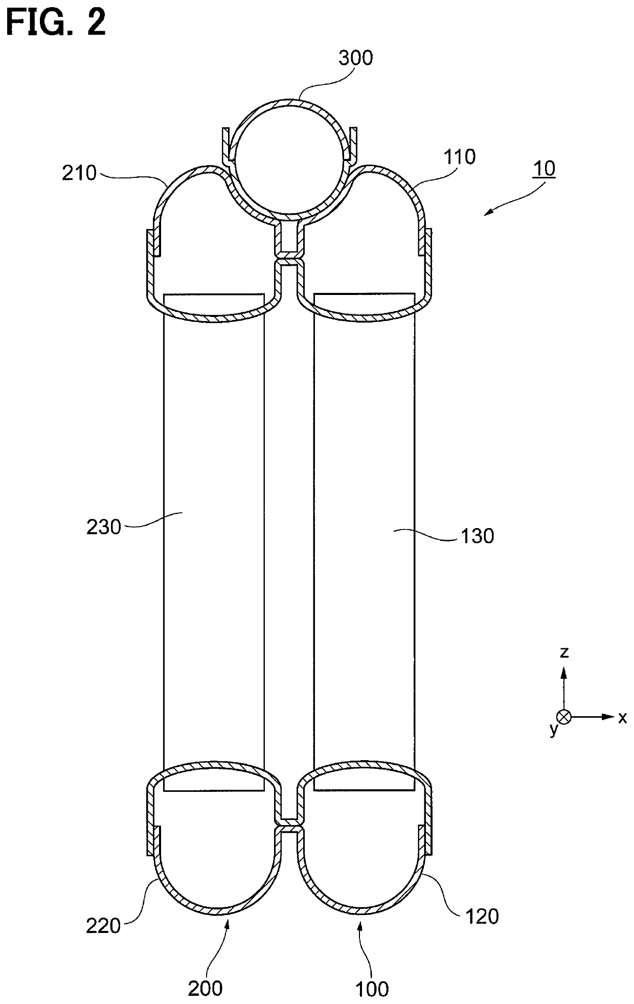
[0025]Configurations of the evaporator 10 will be described referring to FIGS. 1 and 2. FIG. 1 is a perspective view illustrating a whole structure of the evaporator 10. FIG. 2 is a cross-sectional view schematically illustrating the evaporator 10 taken at a center (a cente...


PUM


Abstract

An evaporator has an outer peripheral side held by a holding portion. The evaporator includes a body portion and a packing located on a part of the body portion that faces to the holding portion. The packing includes an inner elastic layer and an outer elastic layer. The inner elastic layer has a water absorbability smaller than that of the outer elastic layer and is made of a closed cell foam member. The outer elastic layer is made of an open cell foam member. The holding portion includes a first rib preventing an air from flowing along the outer peripheral side of the body portion, and a second rib preventing a displacement of the body portion. A thickness of the outer elastic layer in a condition where the outer elastic layer is not held by the holding portion is larger than a protrusion length of the first rib.

Description

CROSS REFERENCE TO RELATED APPLICATIONS[0001]This application is a U.S. National Phase Application under 35 U.S.C. 371 of International Application No. PCT / JP2016 / 002040 filed on Apr. 15, 2016 and published in Japanese as WO 2016 / 166987 A1 on Oct. 20, 2016. This application is based on and claims the benefit of priority from Japanese Patent Application No. 2015-084847 filed on Apr. 17, 2015. The entire disclosures of all of the above applications are incorporated herein by reference.TECHNICAL FIELD[0002]The present disclosure relates to an evaporator used as a part of an air conditioning system such as an automobile air conditioner.BACKGROUND ART[0003]An air conditioning system installed in a vehicle is required to be small as a whole due to a limitation of a space. Additionally, the air conditioning system is required to be light for improving a fuel economy of a vehicle. To meet these requirements, in recent years, the evaporator is made light in weight by using a thin material, f...

Claims


Application Information

Patent Timeline
Patent Type & Authority Patents(United States)
IPC IPC(8): B60H1/32F28D21/00F25B39/02F28F9/02F28F9/00F28D1/053
CPCF28F9/02B60H1/32F25B39/02F28F2275/02F28F2275/143F28F9/002F28D1/05383F28D1/05391F25B2500/12F28D2021/0085F28F2275/14F28F2265/28F28F2265/30
Inventor NISHINO, TATSUHIKOAKIYOSHI, GOUKIKUWAYAMA, AKINORI
Owner DENSO CORP
Why Eureka
Try Eureka