Magnetometer

a magnetometer and optical sensor technology, applied in the field of magnetometers, can solve the problems of increasing the size of various kinds of devices, and achieve the effect of improving sensitivity and enhancing fluorescence collection efficiency

Active Publication Date: 2019-12-10
RENESAS ELECTRONICS CORP
View PDF8 Cites 5 Cited by
  • Summary
  • Abstract
  • Description
  • Claims
  • Application Information

AI Technical Summary

Benefits of technology

[0007]At the same time, fluorescence which is radiated from four side surfaces of the diamond crystal, which are orthogonal to the incidence direction of the excitation light, is also detected by the low-pass filters and the photodiodes which are provided for respective surfaces. In this manner, fluorescence collection efficiency is enhanced, so that the sensitivity improvement can be achieved.
[0014]According to the above-described one embodiment, miniaturization of a magnetometer can be achieved.

Problems solved by technology

This causes a problem of increasing a size of various kinds of devices formed by using the magnetometer.

Method used


Image

  • Magnetometer
  • Magnetometer
  • Magnetometer

Examples


first embodiment

[0058]

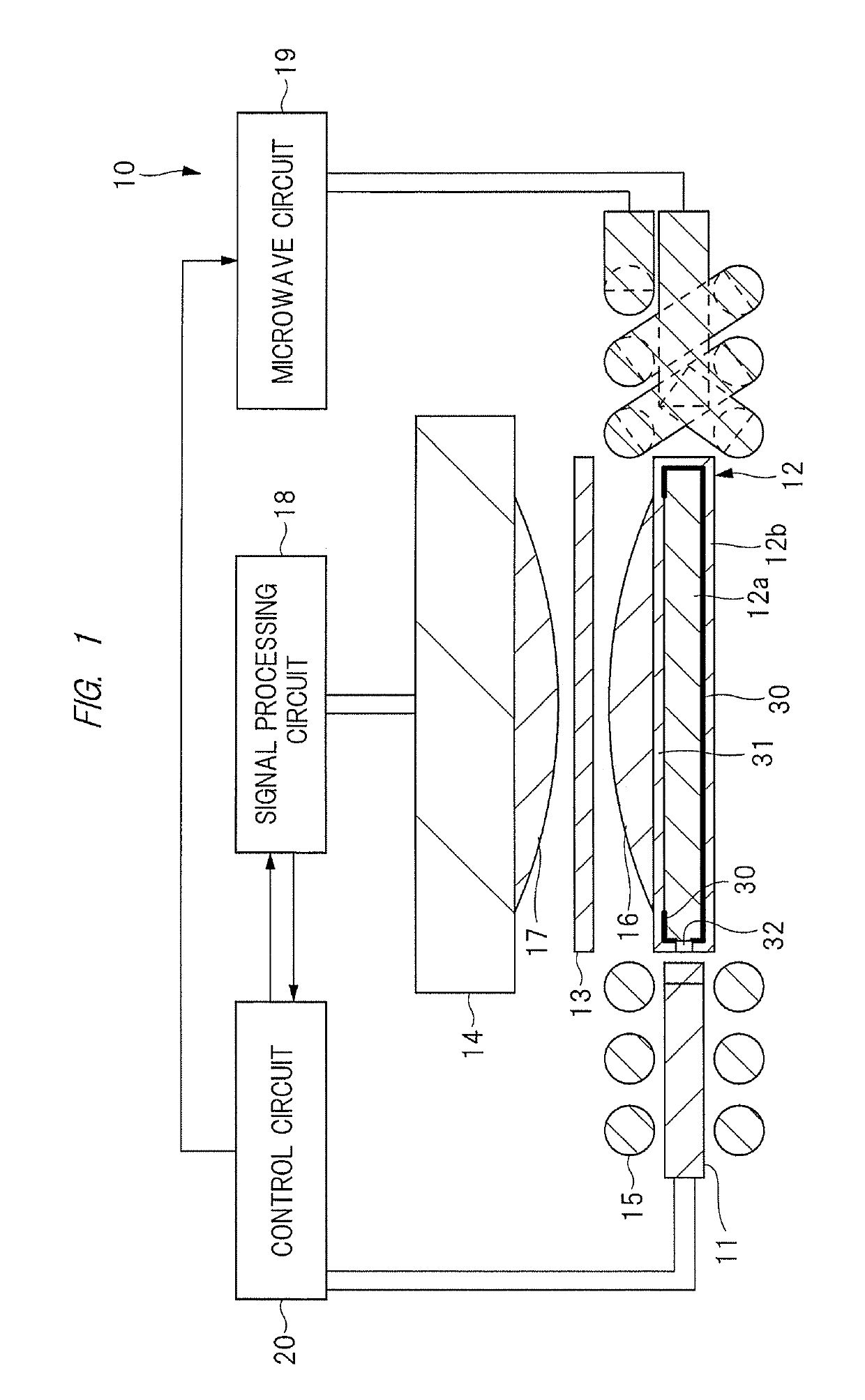
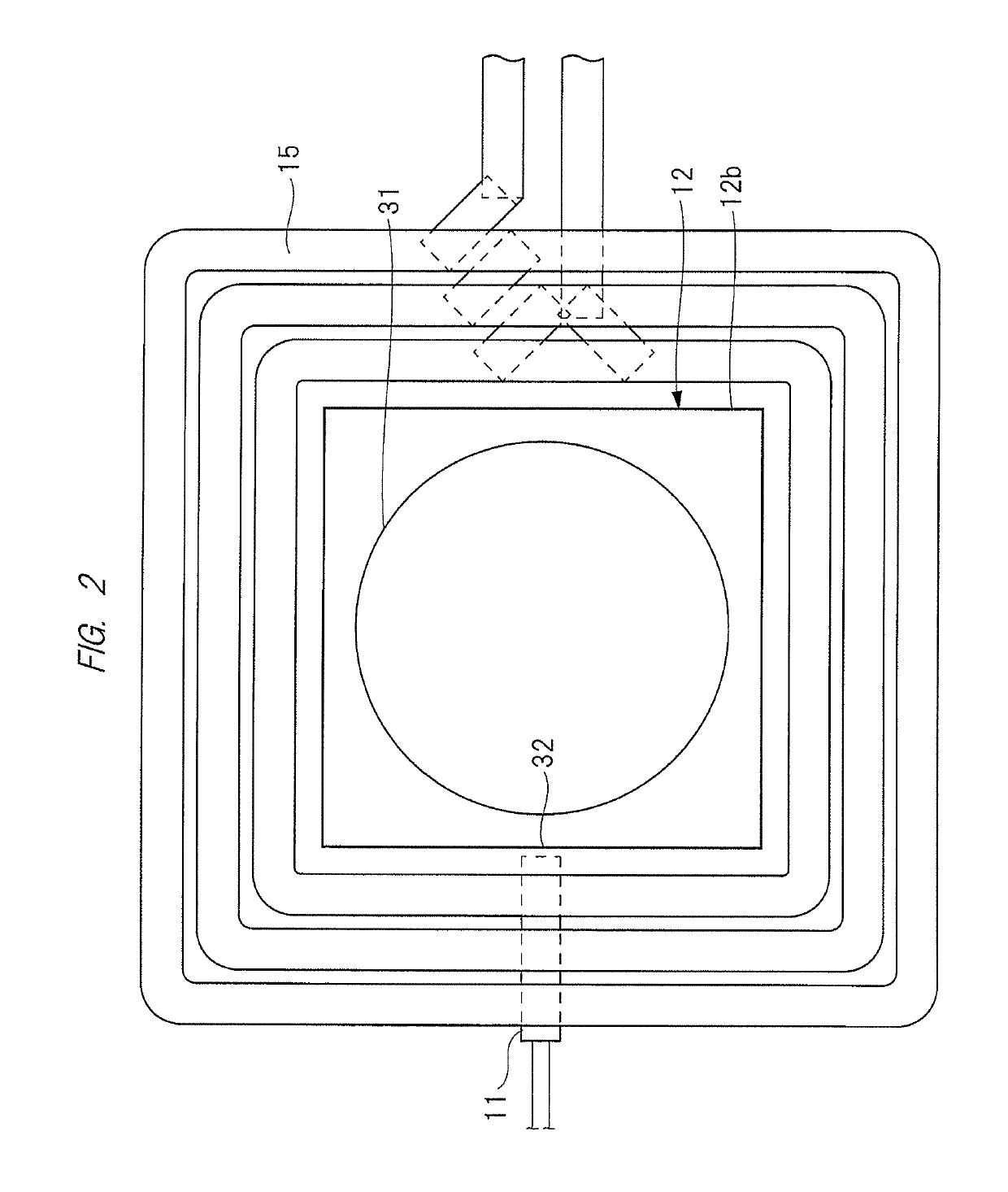
[0059]FIG. 1 is an explanatory drawing showing an example of a structure of a magnetometer according to a first embodiment. FIG. 2 is a plan view of a diamond sensor unit and a microwave coil included in the magnetometer shown in FIG. 1.

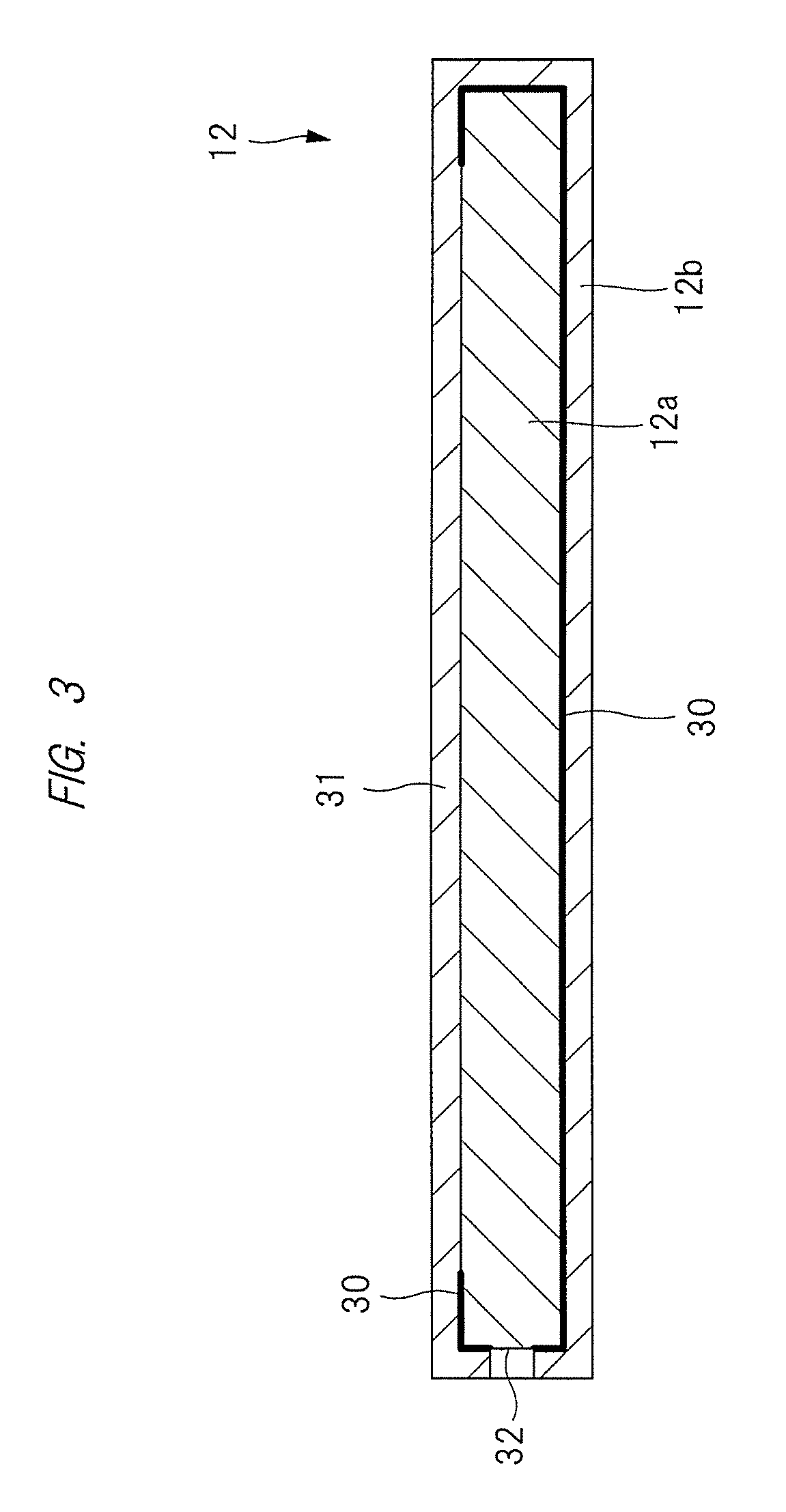
[0060]A magnetometer 10 has a module package structure, and the magnetometer 10 is made thinner and smaller. As shown in FIG. 1 and FIG. 2, the magnetometer 10 includes an excitation light source 11, a diamond sensor unit 12, a low-pass filter 13, a photodiode 14, a microwave coil 15, lenses 16 and 17, a signal processing circuit 18, a microwave circuit 19, and a control circuit 20.

[0061]The lens 16 which is a first lens is provided on the diamond sensor unit 12. More specifically, the lens 16 is provided on a fluorescence output window 31 formed in a diamond sensor case 12b described later.

[0062]The low-pass filter 13 is provided above the lens 16 at a certain distance from the lens 16. The photodiode 14 which is a fluorescence intensity detec...

second embodiment

[0125]

[0126]In the structure according to the first embodiment described above, excitation light is incident from a side surface of the diamond sensor case 12b. Meanwhile, a technique for allowing excitation light to be incident obliquely from above the diamond sensor case 12b will be described in the second embodiment.

[0127]

[0128]FIG. 6 is an explanatory drawing showing an example of across section of the magnetometer 10 according to the second embodiment. FIG. 7 is a plan view of FIG. 6. Note that the signal processing circuit 18, the microwave circuit 19, and the control circuit 20 are omitted for simplification in FIG. 6 and FIG. 7.

[0129]A difference between the magnetometer 10 shown in FIG. 6 and the magnetometer 10 in FIG. 1 according to the first embodiment described above lies in that excitation light from the excitation light source 11 is not incident on a side surface of the diamond sensor case 12b, but incident obliquely from above a back surface of the diamond sensor cas...

third embodiment

[0143]

[0144]The magnetometer 10 according to the first embodiment described above has a structure in which one lens is provided for one diamond sensor unit 12. Meanwhile, a case in which a plurality of lenses are provided for one diamond sensor unit 12 will be described in the third embodiment.

[0145]

[0146]FIG. 8 is an explanatory drawing showing an example of a cross section of the magnetometer 10 according to the third embodiment. FIG. 9 is a plan view of FIG. 8. FIG. 9 is a plan view of the magnetometer 10 viewed from a magnetism measurement surface, that is, a main surface of the diamond sensor 12a. Note that the signal processing circuit 18, the microwave circuit 19, and the control circuit 20 are omitted for simplification in FIG. 8 and FIG. 9.

[0147]A difference between the magnetometer 10 shown in FIG. 8 and FIG. 9 and the magnetometer 10 in FIG. 1 and FIG. 2 according to the above-described first embodiment lies in that each of the lenses 16 and 17 is not formed of a single l...


PUM


Abstract

A magnetometer includes a diamond sensor, an excitation light source, a diamond sensor case, and a photodiode. The excitation light source irradiates the diamond sensor case with excitation light. In the diamond sensor case, a reflection film which reflects excitation light is formed on either a front surface or an inner surface, and the diamond sensor is stored. The photodiode detects intensity of fluorescence generated from the diamond sensor. The diamond sensor case includes a fluorescence output window and an excitation-light reception window. Fluorescence generated by the diamond sensor is output through the fluorescence output window. Excitation light emitted by the excitation light source is received through the excitation-light reception window. The photodiode is provided on a side of a second surface opposite to a first surface which is a magnetism measurement surface of the diamond sensor.

Description

CROSS-REFERENCE TO RELATED APPLICATION[0001]The present application claims priority from Japanese Patent Application No. 2016-026993 filed on Feb. 16, 2016, the content of which is hereby incorporated by reference into this application.TECHNICAL FIELD OF THE INVENTION[0002]The present invention relates to a magnetometer, and particularly relates to an effective technique in miniaturizing a highly-sensitive magnetic sensor using nitrogen-vacancy centers of a diamond crystal.BACKGROUND OF THE INVENTION[0003]For a highly-sensitive magnetometer which is operable at a room temperature, a diamond crystal including nitrogen-vacancy centers (NV centers) has been proposed (see, for example, D. Sage et al., “Efficient photon detection from color centers in a diamond optical waveguide” PHYSICAL REVIEW B 85, 121202(R) (2012) (Non-Patent Document 1)).[0004]The Non-Patent Document 1 discloses that, by detecting fluorescence generated from a diamond crystal while irradiating the diamond crystal wi...

Claims


Application Information

Patent Timeline
Patent Type & Authority Patents(United States)
IPC IPC(8): G01R33/032G01R33/12A61B5/00
CPCG01R33/032G01R33/1284A61B5/0071
Inventor HATANO, YUJIYOSHINO, TAKASHI
Owner RENESAS ELECTRONICS CORP
Why Eureka
Try Eureka