
Beveled chip reflector for chip-scale packaging light-emitting device and manufacturing method of the same

a technology of light-emitting devices and beveled reflectors, which is applied in the direction of semiconductor devices, basic electric elements, electrical equipment, etc., can solve the problems of csp leds that are difficult to apply to csp leds, more light energy loss in csp, and manufacturing techniques that can usually be utilized to form leds, etc., to achieve the effect of improving the luminous efficacy of top-surface emitting csp leds

Active Publication Date: 2019-12-31
MAVEN OPTRONICS CO LTD
View PDF29 Cites 0 Cited by
  • Summary
  • Abstract
  • Description
  • Claims
  • Application Information

AI Technical Summary

Benefits of technology

The solution effectively increases luminous efficacy by guiding laterally radiated light towards the top surface, reducing energy loss, and improving thermal management, while maintaining a small form factor and low production costs.

Problems solved by technology

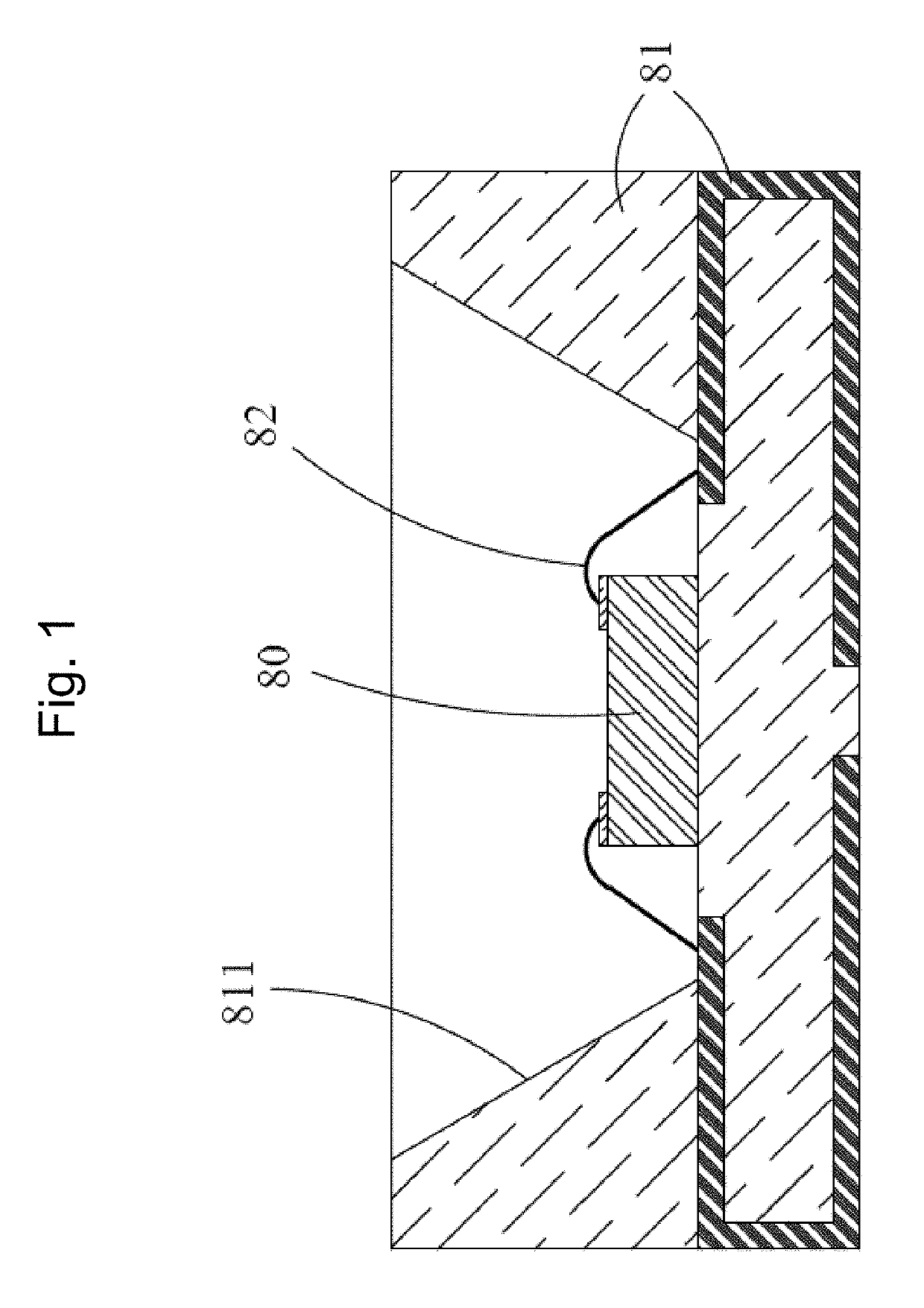
Although the luminous efficacy of the PLCC LED package can be effectively increased through the reflective cup 811 with a beveled reflective surface surrounding the light-emitting semiconductor die 80, the PLCC LED package has its inherent limitations, including: (1) large differences in paths of the primary light emitted from the light-emitting semiconductor die 80 travelling in a photoluminescent material along various radiation angles resulting in poor color uniformity, and ultimately resulting in yellow halo ring; (2) the light-emitting area of the LED package is much larger than the light-emitting semiconductor die area, resulting in a larger etendue, so that a design of a secondary optical lens to shape the radiation pattern is not easy; and (3) large thermal resistance of the lead frame structure 81 will cause heat dissipation to be ineffective and eventually lead to decay of luminous efficacy.
However, as the size of the CSP LED shrinks, the manufacturing techniques that can usually be utilized to form LEDs, such as the beveled reflector design of the PLCC LED package, will become difficult to be applied to the CSP LEDs.
After multiple reflections inside the semiconductor die, the light can be guided toward and can escape from the top surface of the photoluminescent layer out of the CSP LED, therefore resulting in more light energy loss in the CSP LED and reducing the overall luminous efficacy.

Method used


Image

  • Beveled chip reflector for chip-scale packaging light-emitting device and manufacturing method of the same
  • Beveled chip reflector for chip-scale packaging light-emitting device and manufacturing method of the same
  • Beveled chip reflector for chip-scale packaging light-emitting device and manufacturing method of the same

Examples


Embodiment Construction

Definitions

[0035]The following definitions apply to some of the technical aspects described with respect to some embodiments of the disclosure. These definitions may likewise be expanded upon herein.

[0036]As used herein, the singular terms “a,”“an,” and “the” may include plural referents unless the context clearly dictates otherwise. Thus, for example, reference to a layer can include multiple layers unless the context clearly dictates otherwise.

[0037]As used herein, the term “set” refers to a collection of one or more components. Thus, for example, a set of layers can include a single layer or multiple layers. Components of a set also can be referred to as members of the set. Components of a set can be the same or different. In some instances, components of a set can share one or more common characteristics.

[0038]As used herein, the term “adjacent” refers to being near or adjoining. Adjacent components can be spaced apart from one another or can be in actual or direct contact with ...


PUM


Abstract

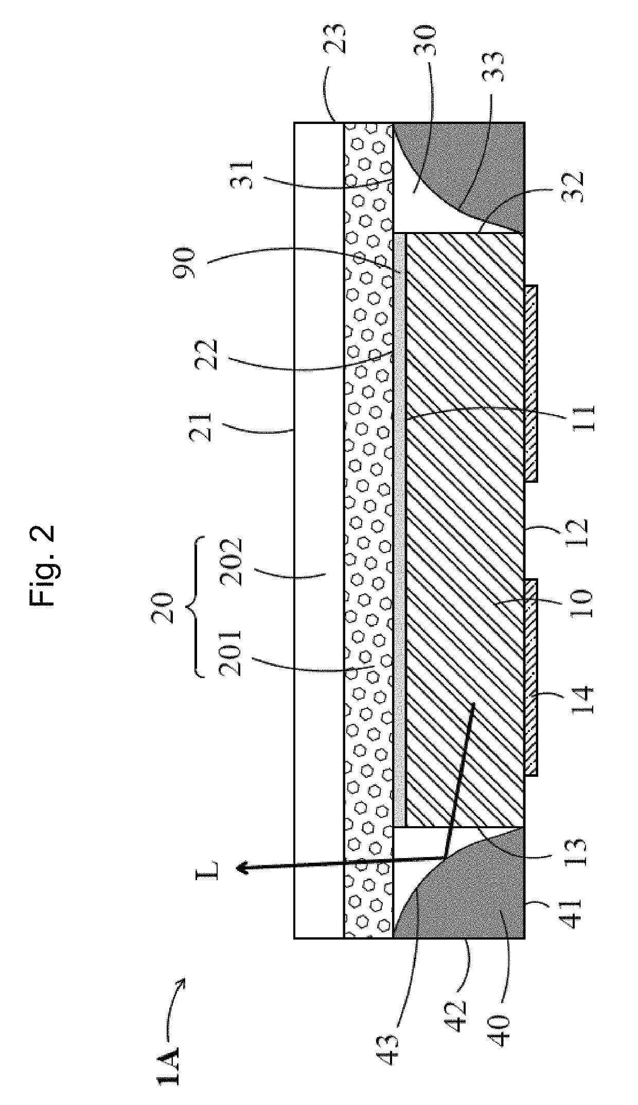
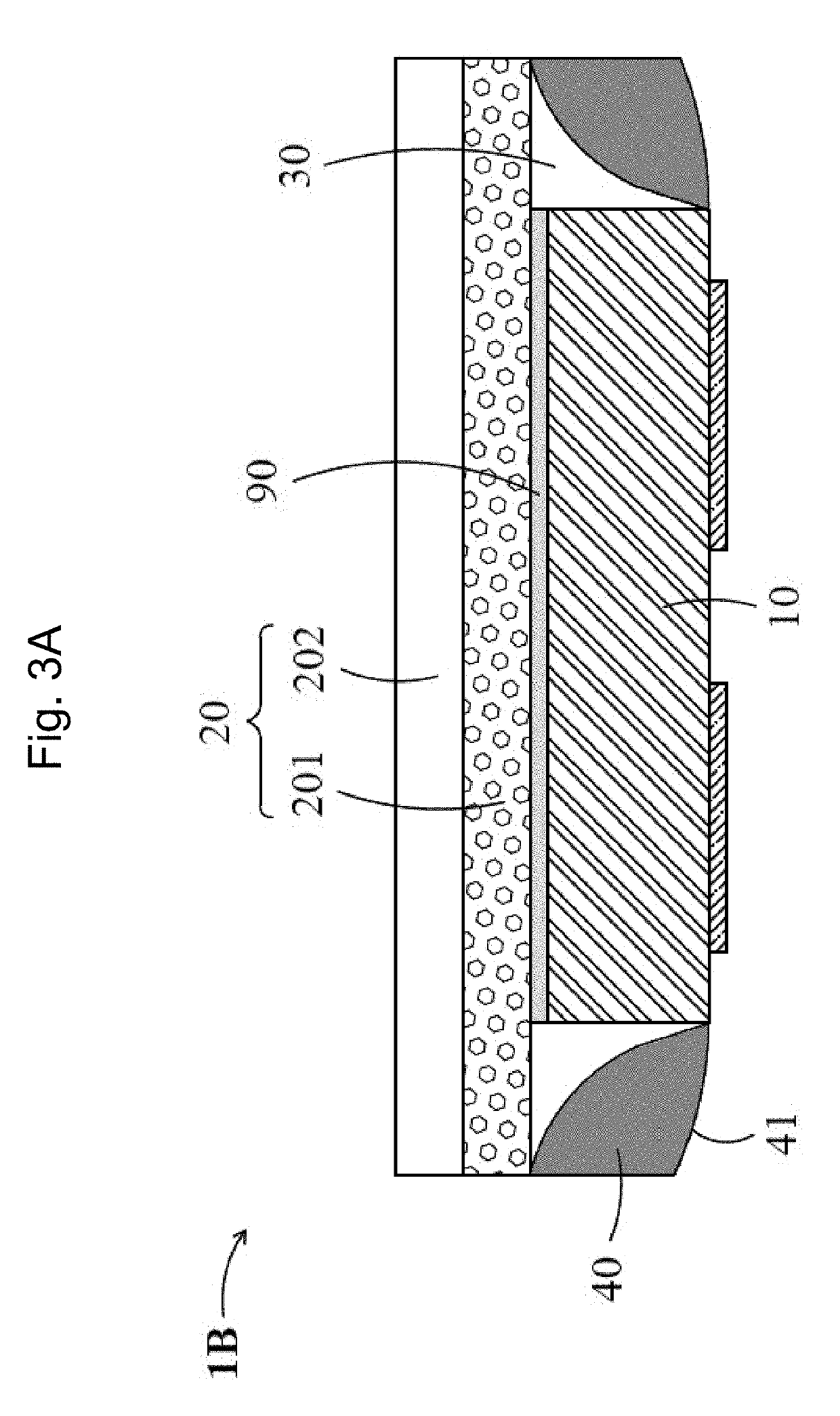
A chip-scale packaging (CSP) light-emitting device (LED), including a light-emitting semiconductor die, a photoluminescent layer, a chip-side-spacer structure, and a beveled chip reflective structure, is disclosed. The beveled reflective structure is disposed surrounding the chip-edge surfaces of the light-emitting semiconductor die, wherein the chip-side-spacer structure is disposed between the beveled reflective structure and the chip-edge surfaces of the light-emitting semiconductor die. A manufacturing method to fabricate the CSP LED is also disclosed. The CSP LED with a beveled chip reflector can effectively reflect the light radiated from the light-emitting semiconductor die toward the photoluminescent layer so that the light extraction efficiency is improved.

Description

CROSS-REFERENCES TO RELATED APPLICATIONS[0001]This application claims the benefit of and priority to Taiwan Patent Application No. 106103239 filed on Jan. 26, 2017, and Chinese Patent Application No. 201710057384.4 filed on Jan. 26, 2017, the disclosures of which are incorporated herein by reference in their entirety.BACKGROUND[0002]Technical Field[0003]The present disclosure relates to a light-emitting device and a method of manufacturing the same, and more particularly, to a chip-scale packaging light-emitting device having a beveled chip reflector and a method of manufacturing the same.[0004]Description of the Related Art[0005]Light-emitting devices (LEDs) are commonly used as light sources for illumination, backlighting, or indicators, and light-emitting semiconductor dies are typically disposed inside a package structure to become an LED package or further encapsulated or covered by photoluminescent materials as a white LED package.[0006]Through a proper design, an LED can achi...

Claims


Application Information

Patent Timeline
Patent Type & Authority Patents(United States)
IPC IPC(8): H01L33/62H01L33/48H01L33/00H01L33/56H01L33/50H01L33/54H01L33/60
CPCH01L33/508H01L33/60H01L33/505H01L33/56H01L33/486H01L33/507H01L33/62H01L33/54H01L33/0095H01L2933/0066H01L2933/0033H01L2933/0041H01L2933/0058H01L2224/48091H01L2924/00014
Inventor CHEN, CHIEHWANG, TSUNG-HSI
Owner MAVEN OPTRONICS CO LTD
Learn More