Electrohydraulic valve and method for producing the electrohydraulic valve

a technology of electrohydraulic valves and valve shells, applied in the direction of valve details, valve housings, non-electric welding apparatus, etc., to achieve the effects of reducing leakage, avoiding leakage, and improving joining force and radial strength

Active Publication Date: 2020-01-07
ECO HLDG 1 GMBH
View PDF11 Cites 0 Cited by
  • Summary
  • Abstract
  • Description
  • Claims
  • Application Information

AI Technical Summary

Benefits of technology

[0008]Thus, it is an object of the invention to provide an electrohydraulic valve with an electromagnetic actuator assembly and a hydraulic assembly, in particular an electro hydraulic valve of a cam phaser which reliably seals the electromagnetic actuator assembly relative to the hydraulic assembly and the ambient and which eliminates possible leakages and which has an improved joining force and radial strength over he operating temperature range of the electro hydraulic valve over the prior art. It is another object of the invention to provide an energy efficient and quick method for producing the electro hydraulic valve and in particular for producing a connection of the electromagnetic actuator assembly with the hydraulic assembly which is also suitable for producing large production volumes.

Problems solved by technology

A certain unpredictability of the connection, however, is disadvantageous and thus a crimped connection is typically used where only small mechanical loads occur.

Method used


Image

  • Electrohydraulic valve and method for producing the electrohydraulic valve
  • Electrohydraulic valve and method for producing the electrohydraulic valve
  • Electrohydraulic valve and method for producing the electrohydraulic valve

Examples


first embodiment

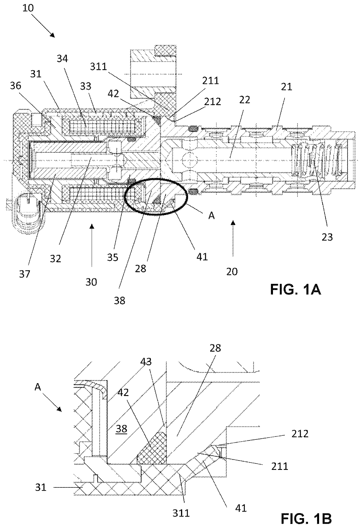
[0056]The actuator housing 31 of the actuator assembly 30 envelops the actuator assembly 30. In the first embodiment according to FIGS. 1A-2B the actuator housing 31 is configured integrally in one piece from the same material. The actuator housing 31 of the actuator assembly 30 is produced as an injection molded component from a thermoplastic synthetic material. The actuator housing 31 is used for producing the friction locking and form locking connection of the actuator housing 31 of the actuator assembly 30 with the valve housing 21 of the hydraulic assembly in that the actuator housing 31 is ultrasonically welded with the valve housing 21.

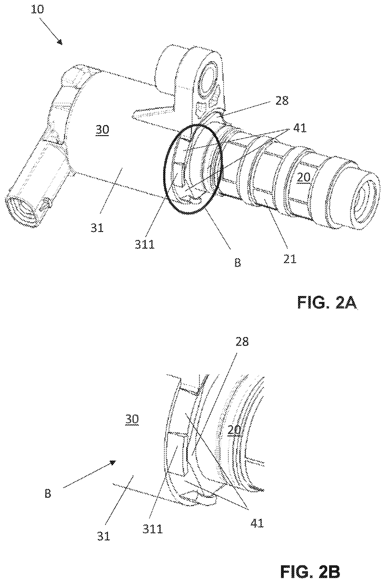
[0057]As evident from FIG. 2A and 2B the actuator housing 31 of the actuator group 30 includes a plurality of pre-segmented bars 41. The bars 41 are configured within an annular overhang 311 of the actuator housing 31 which partially reaches around the valve housing 21. The bars 41 are configured so that they can reach over and behind undercuts...

second embodiment

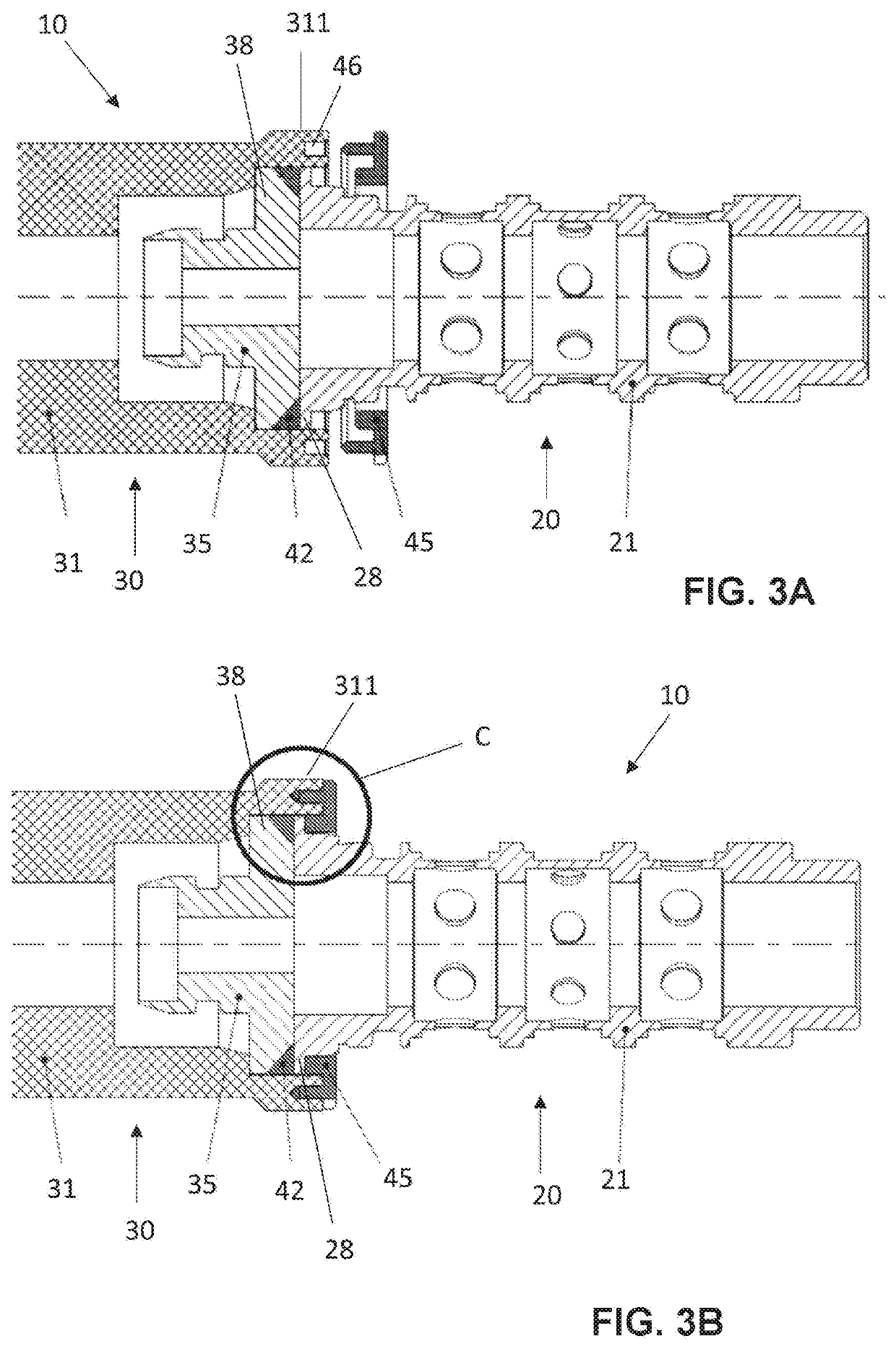
[0064]FIGS. 3A-3C illustrate an electro hydraulic valve. Thus, a friction locking and / or form locking connection of the actuator assembly 30 with the hydraulic assembly 20 is established by ultrasonically welding an additional connection element 45 with the overhang 311 of the actuator housing 31 of the actuator assembly 30 that is oriented towards the hydraulic assembly 20 and with the valve housing 21.

[0065]FIG. 3A illustrates a longitudinal sectional view of the actuator assembly 30 and the hydraulic assembly 20 of the second embodiment of the electro hydraulic valve 10 in a non-connected condition. The additional connection element 45 is formed in the illustrated embodiment by a one-piece thermoplastic synthetic material ring. In a non-illustrated alternative, the additional connection element is formed by a multicomponent ring. The connection element 45 is ultrasonically welded together with the overhang 311 of the actuator housing 31 of the actuator assembly 30 that is oriente...


PUM

PropertyMeasurementUnit
frictionaaaaaaaaaa
joining forceaaaaaaaaaa
radial strengthaaaaaaaaaa

Abstract

An electro hydraulic valve for a cam phaser, including an electromagnetic actuator assembly, and a hydraulic assembly, wherein the electromagnetic actuator assembly and the hydraulic assembly are arranged axially aligned along a longitudinal axis, wherein the hydraulic assembly includes a valve housing in which a valve piston is arranged axially movable along the longitudinal axis, wherein a plunger for positioning the valve piston along the longitudinal axis is arranged within the electromagnetic actuator assembly, and wherein the electromagnetic actuator assembly and the hydraulic assembly are connected with one another indirectly or directly, wherein the electromagnetic actuator assembly includes an actuator housing and a friction or form locking connection of the electromagnetic actuator assembly with the hydraulic assembly is provided by an ultrasonic weld between the actuator housing and the valve housing.

Description

RELATED APPLICATIONS[0001]This application claims priority from and incorporates by reference German patent application[0002]DE 10 2017 119 082.1 filed on Aug. 21, 2017 and[0003]DE 10 2018 110 755.2 filed on May 4, 2018,both of which are incorporated in their entirely by this reference.FIELD OF THE INVENTION[0004]The invention relates to an electrohydraulic valve, in particular an electrohydraulic valve of a cam phaser.BACKGROUND OF THE INVENTION[0005]Generic electro hydraulic valves are known from DE 10 2014 010 876 B3 and DE 10 2009 043 320 A1.[0006]When mounting the electromagnetic actuator assembly and the hydraulic assembly typically a friction locking and form locking connection is generated in an end position of both subassemblies. Typically the friction locking and form locking connection is provided by sextuple or quadruple crimping of the valve housing and a portion of the metal sleeve that protrudes beyond the magnet housing. Thus, the two components are connected with ea...

Claims


Application Information

Patent Timeline
Patent Type & Authority Patents(United States)
IPC IPC(8): F01L1/46F16K27/04F15B13/043F01L1/344B23P15/00B23K20/10F15B13/00
CPCF01L1/46B23P15/001F01L1/344B23K20/10F01L1/3442F16K27/048F15B13/0435F01L2001/3443F01L2103/00F15B13/00F01L2101/00F16K27/029F16K31/0675F16K27/00F01L2301/00F01L2303/00
Inventor GOLL, JUERGENNICKEL, SEBASTIANSELKE, ANDRE
Owner ECO HLDG 1 GMBH
Why Eureka
Try Eureka