Image forming apparatus

Active Publication Date: 2020-02-11
FUJIFILM BUSINESS INNOVATION CORP
View PDF6 Cites 0 Cited by
  • Summary
  • Abstract
  • Description
  • Claims
  • Application Information

AI Technical Summary

Benefits of technology

The patent is about an image forming apparatus that reduces the amount of small particles released into the atmosphere. The apparatus uses a special belt fixing unit and a special toner that contains a release agent with a melting temperature of 60 to 100 degrees Celsius. This results in a decrease in the amount of small particles (UFPs) that are released from the apparatus compared to an apparatus that doesn't have a particle charging unit and a particle collecting unit.

Problems solved by technology

In such an image forming apparatus, however, heat is transferred from the belt fixing unit to the recording medium, and temperature therefore tends to be high in a region upstream of the nipping region in the transport direction of the recording medium, and thus the release agent having a low melting temperature is easily evaporated in such a region.
However, aspects of the non-limiting embodiments are not required to address the advantages described above, and aspects of the non-limiting embodiments of the present disclosure may not address advantages described above.

Method used


Image

  • Image forming apparatus
  • Image forming apparatus
  • Image forming apparatus

Examples


examples

[0303]The present disclosure will now be further specifically described in detail with reference to Examples and Comparative Examples but is not limited thereto at all.

Preparation of Crystalline Resin (A)

[0304]Into a three-neck flask, 100 parts by mass of dimethyl sebacate, 67.8 parts by mass of hexanediol, and 0.10 parts by mass of dibutyltin oxide are put. The mixture is reacted at 185° C. for 5 hours under nitrogen atmosphere while water generated in the reaction is removed to the outside. Then, the temperature is increased up to 220° C. while the pressure is gradually reduced, and the resulting product is further reacted for 6 hours and then cooled. Through this process, a crystalline resin (A) having a weight average molecular weight of 33,700 is prepared.

Preparation of Amorphous Resin

Preparation of Amorphous Resin (1)

[0305]Into a three-neck flask, 61 parts by mass of dimethyl terephthalate, 75 parts by mass of dimethyl fumarate, 34 parts by mass of dodecenylsuccinic anhydride,...

examples a1

to A5

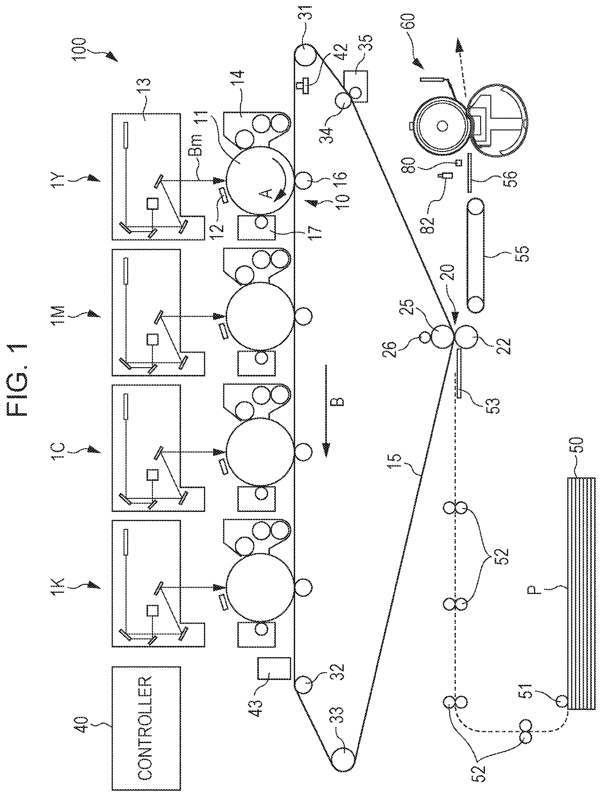
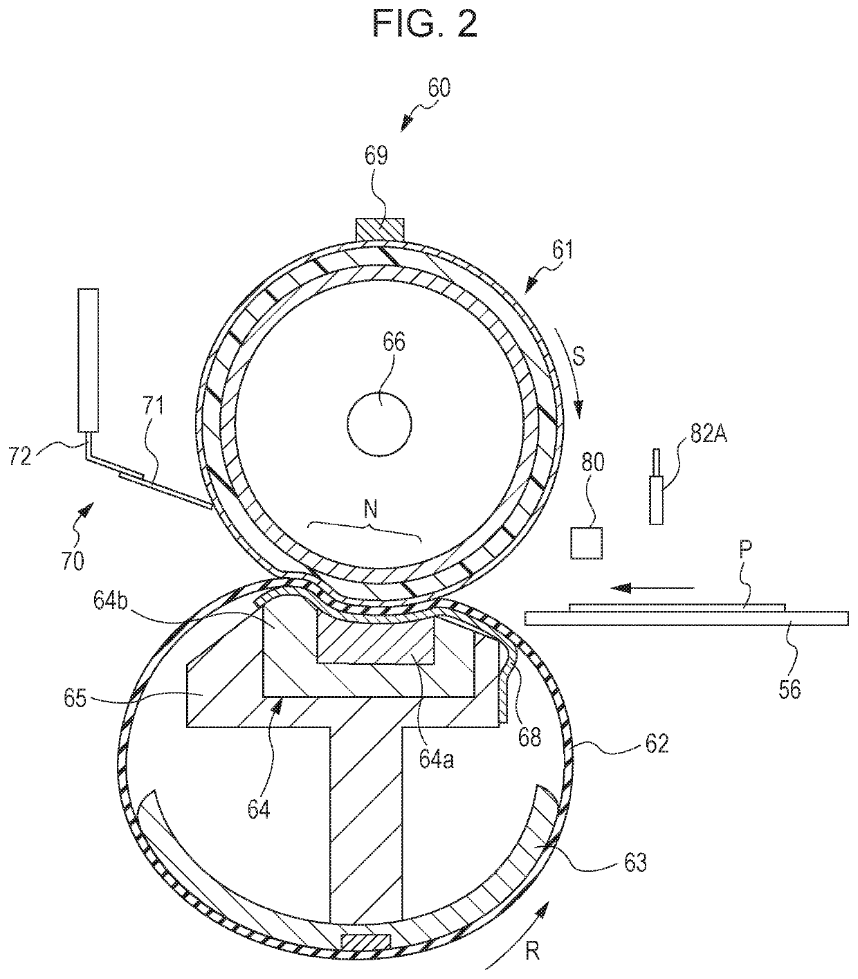
[0326]An image forming apparatus (trade name: 700 DIGITAL COLOR PRESS, manufactured by Fuji Xerox Co., Ltd.) is modified into an image forming apparatus that includes a fixing device having a similar structure to the fixing device illustrated in FIG. 2 (also referred to as “fixing device A”), a charger, and a particle collecting device.

[0327]Specifically, the image forming apparatus is modified so as to have the charger and particle collecting device that are disposed in the vicinity of the nipping region, which is formed between the heating roller and the pressure belt, and upstream of the nipping region in the transport direction of a recording medium as illustrated in FIG. 2. In addition, a filter attached to an exhaust outlet of the image forming apparatus is removed.

[0328]In the modified image forming apparatus, the minimum distance from the upstream end of the nipping region in the transport direction to the charger is 35 mm, and the minimum distance from the transport pa...

examples b1 to b5

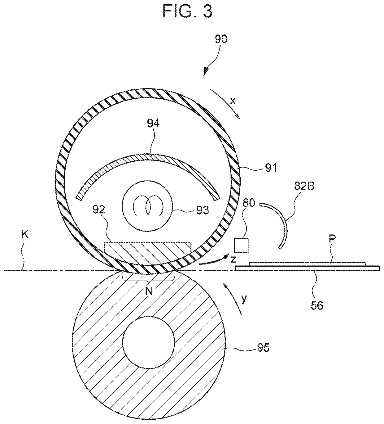
[0332]An image forming apparatus (trade name: 700 DIGITAL COLOR PRESS, manufactured by Fuji Xerox Co., Ltd.) is modified into an image forming apparatus that includes a fixing device having a similar structure to the fixing device illustrated in FIG. 3 (also referred to as “fixing device B”), a charger, and a particle collecting device.

[0333]Specifically, the charger and particle collecting device are disposed in the vicinity of the nipping region, which is formed between the heating belt and the pressure roller, and upstream of the nipping region in the transport direction of a recording medium as illustrated in FIG. 3. In addition, a filter attached to an exhaust outlet of the image forming apparatus is removed.

[0334]In the modified image forming apparatus, the minimum distance from the upstream end of the nipping region in the transport direction to the charger is 35 mm, and the minimum distance from the transport path of paper to the charger is in the range of 10 mm to 40 mm. Th...


PUM

PropertyMeasurementUnit
Temperatureaaaaaaaaaa

Abstract

An image forming apparatus includes an image holding member, a charging unit that charges the surface of the image holding member, an electrostatic latent image forming unit that forms an electrostatic latent image on the charged surface of the image holding member, a developing unit that includes a developer containing toner particles containing a release agent having a melting temperature ranging from 60° C. to 100° C. and that develops the electrostatic latent image on the surface of the image holding member with the developer to form a toner image, a transferring unit that transfers the toner image to a recording medium, a fixing unit that includes two members of which the outer surfaces are in contact with each other to form a nipping region and of which at least one member is a belt member and that allows the recording medium having the transferred toner image to pass through the nipping region to fix the toner image to the recording medium, a particle charging unit that is disposed in the vicinity of the nipping region and upstream of the nipping region in the transport direction of the recording medium so as to face the toner-image-formed side of the recording medium and that charges particles, and a particle collecting unit that is disposed near the particle charging unit and that is charged to the opposite polarity to the charged particles.

Description

CROSS-REFERENCE TO RELATED APPLICATIONS[0001]This application is based on and claims priority under 35 USC 119 from Japanese Patent Application No. 2018-159221 filed Aug. 28, 2018.BACKGROUND(i) Technical Field[0002]The present disclosure relates to an image forming apparatus.(ii) Related Art[0003]An electrophotographic process for forming an image, for example, includes charging the surface of an image holding member, forming an electrostatic latent image on this surface of the image holding member on the basis of image information, developing the electrostatic latent image with a developer containing toner to form a toner image, and transferring and fixing the toner image to the surface of a recording medium.[0004]Japanese Laid Opened Patent Application Publication No. 2017-15802 discloses an image forming apparatus including an exhaust channel that introduces air discharged from a fixing device to the outside, the fixing device heating toner transferred to a sheet to fix the toner...

Claims


Application Information

Patent Timeline
IPC IPC(8): G03G15/20G03G21/10G03G9/087G03G9/08
CPCG03G9/08755G03G9/0819G03G15/2017G03G21/10G03G9/08782G03G9/0827G03G2215/2003G03G21/206G03G9/08797
Inventor KITAJIMA, KATSUYUKIKURIBAYASHI, MASATAKAKOIDE, TAKAFUMIYAWADA, TEPPEIOSHIMA, SHOTA
Owner FUJIFILM BUSINESS INNOVATION CORP
Why Eureka
Try Eureka