Luminous pressure sensor and touch control button thereof, and electronic device

a technology of luminous pressure sensor and touch control button, which is applied in the direction of electronic switching, pulse technique, instruments, etc., can solve the problems of affecting the large-scale adoption of luminous pressure sensors, the improvement of the use cost of pressure sensors, etc., and achieves simple structure, improved user experience, and overall aesthetics. improved

Active Publication Date: 2020-02-18
SHENZHEN NEW DEGREE TECH
View PDF17 Cites 1 Cited by
  • Summary
  • Abstract
  • Description
  • Claims
  • Application Information

AI Technical Summary

Benefits of technology

[0029]The luminous pressure sensor provided by the present application, by the arrangement of the feedback assembly and a pressing structure, not only can ensure the pressing sensitivity but also emits light when in use; actual working conditions can be timely acquired, overall aesthetic property can be further improved, and thus users' experience can be improved. Meanwhile, the feedback assembly is integrated with the sensing plate by the first connecting adhesive layer, and the pressure sensing layer is integrated with the sensing plate by the second connecting adhesive layer, the structure is simple and the assembly is convenient; a reliable and steady pressure sensor can be obtained without complex structural processing and assembling processes, manufacture difficulty and cost are lowered, the pressure sensor can be promoted to use at a large scale, and the function range of the product is expanded.
[0030]The touch control button and electronic device produced using the above-mentioned luminous pressure sensor have a higher control precision and a better operational reliability, and can emit light in use, such that users' enthusiasm of using the luminous pressure sensing technique can be improved, the difficulty of the users' application can be lowered, and users' or customers' experience during the pressing operation can be enriched.

Problems solved by technology

These pressure sensors require being realized by special methods, which greatly improves the using cost of the pressure sensors and hinders large-scale adoption of luminous pressure sensors.

Method used


Image

  • Luminous pressure sensor and touch control button thereof, and electronic device
  • Luminous pressure sensor and touch control button thereof, and electronic device
  • Luminous pressure sensor and touch control button thereof, and electronic device

Examples


Embodiment Construction

[0041]In order to make the purpose, the technical features and the advantages of the present application be clearer, the present application will be described in detail with reference to accompanying drawings and embodiments. It should be understood that the specific embodiments described herein are used for interpretation of present application merely, rather than the limitation to the present application. For the sake of brevity, many traditional techniques and principles relating to a pressure sensor need not and will not to be described in detail. The term “example” means a paradigm, an instance or an illustration, but not a model or a reasonable imitation.

[0042]The realization of the present invention will be described hereafter with reference to the accompany drawings.

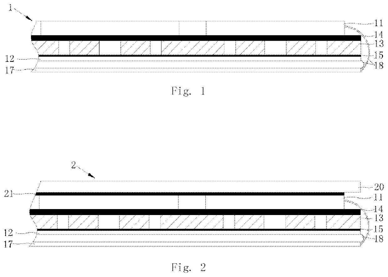
[0043]As shown in FIG. 1, a pressure sensor 1 provided by an embodiment of the application comprises a luminous feedback assembly 11 and a pressure sensing layer 12 for detecting pressure. When the pressure sensi...


PUM

PropertyMeasurementUnit
thicknessaaaaaaaaaa
thicknessaaaaaaaaaa
thicknessaaaaaaaaaa

Abstract

A luminous pressure sensor comprises a feedback assembly capable of emitting light when pressure is applied thereto, and a pressure sensing layer. A sensing plate is provided between the feedback assembly and the pressure sensing layer, and is connected to the feedback assembly and the pressure sensing layer via a connecting adhesive layer. The sensing plate is provided with at least one pressing structure thereon for concentrating pressing force. A touch control button may comprise the luminous pressure sensor, and an electronic device may comprise the touch control button. The luminous pressure sensor has a simple structure and a low manufacturing cost, and is easy to assemble and to commercialize.

Description

[0001]This application is the U.S. national phase of International Application No. PCT / CN2015 / 077956 filed Apr. 30, 2015 which designated the U.S., the entire content of which is hereby incorporated by reference.TECHNICAL FIELD[0002]The present application relates to the technical field of sensor structures, and more particularly, relates to a luminous pressure sensor, a touch control button, and an electronic device equipped therewith.BACKGROUND[0003]At present, pressure sensors are being gradually applied in various fields. Main functions of the pressure sensors are to increase the amount of information, and provide the possibility to detect the level of pressure. By means of pressure operations, switch actions, information encryption and the like can be performed effectively. By adding a luminous system, a visual feedback can be provided timely, an operation interface can be visually pleasing, and user experience can be improved.[0004]In the present industry, there have already b...

Claims


Application Information

Patent Timeline
Patent Type & Authority Patents(United States)
IPC IPC(8): G01L1/26G06F3/041H03K17/96
CPCG06F3/0416G01L1/26H03K17/96H03K2217/96042G06F2203/04105
Inventor LI, HAO
Owner SHENZHEN NEW DEGREE TECH
Why Eureka
Try Eureka