Process for the recovery of rare earth metals from permanent magnets

a technology of rare earth metals and permanent magnets, applied in the field of rare earth metal recovery process from permanent magnets, can solve the problems of large amount of chemicals required in hydrometallurgical processes, significant environmental and economic impacts, and large use of strong acids and large amounts of chemicals, so as to achieve the effect of ensuring magnetic removal

Active Publication Date: 2020-03-03
UNIV HOUSTON SYST
View PDF6 Cites 0 Cited by
  • Summary
  • Abstract
  • Description
  • Claims
  • Application Information

AI Technical Summary

Benefits of technology

[0013]Embodiments of the present invention provide methods for recovering rare earth metals (REMs) from rare earth containing magnets, where the methods include a reaction step, where rare earth metal containing magnets are reacted with a formic acid / water mixture to dissolve rare earth metals and non-rare earth metals from the magnets forming rare earth metal (REM) formates and non-rare earth metal (NREM) formates and / or other NREM components. The REM formate precipitates, while the NREM formates and / or other NREM components are more soluble and either remain in solution or form part of the precipitate. The methods also include filtrating the precipitates from the reaction mixture and washing the precipitate with a solvent to extract any remaining non-rare earth metal formates in the precipitate leaving a purer rare earth formate product, where the solvent is characterized in that the NREM formates and / or other NREM components are more soluble in the solvent than the REM formates. The methods of this invention are economical due to the minimum number of process steps and minimum chemical usage. As the reaction involves a metal reacting with an acid, the reaction generates a stoichiometric amount of hydrogen gas. The hydrogen gas may be disposed of by controlled burning in a combustion unit, feed to a hydrogen fuel cell for energy production, used in a hydrogenation reaction, or captured and stored for subsequent use. Thus, in certain embodiments, the hydrogen gas may be used as a fuel source to supply some or all of the energy needed to heat the reaction vessel.
[0014]The methods of this invention were successfully tested using NdFeB magnets recovered from hard disk drives, but may be used with any type of REM containing magnet products. The methods of this invention may be performed with or without any pretreatment steps, such as demagnetization or protective coating removal. Thus, the methods of this invention are simpler, less environmentally destructive or disruptive, and / or are a more economical approach for recovering rare earth elements from the REM containing magnets such as NdFeB magnets. The experiments have shown that the methods of this invention are capable of recovering at least 75% of the REMs present in the REM containing magnet materials. In certain embodiments, the recovery rate is as least 80% of the REM s present in the REM containing magnet materials. In other embodiments, the recovery rate is as least 85% of the REMs present in the REM containing magnet materials. In other embodiments, the recovery rate is as least 90% of the REMs present in the REM containing magnet materials. In other embodiments, the recovery rate is as least 95% of the REMs present in the REM containing magnet materials. Chemical analysis of the final rare earth product phases has shown that the methods of this invention are capable of recovering REM formates in greater than 90% purity, for example about 99% purity relative to the NREMs.
[0016]Embodiments of the present invention provide systems for recovering REMs from REM containing magnet materials, where the systems include a reaction subsystem, a separation subsystem, and extraction subsystem. The reaction subsystem includes at least one reaction vessel for contacting a REM containing magnet materials with an aqueous formic acid solution or a mixtures of formic acid and water as a reactant composition to dissolve and / or extract the REMs contained in the REM containing magnet materials. The separation subsystem includes at least one separation vessel for removing a precipitate from a liquid. The extraction subsystem includes at least one extraction vessel for removing or extracting residual NREM formates from REM formates. The systems and methods operate on the basis of the differential solubility of the REM formates compared to the NREM formates in the solvent used to remove or extract residual NREM formates from the precipitate resulting in a substantially pure REM formate product. In certain cases, the magnets are coated with a protective coating, typically a copper nickel coating comprising either layers of Cu and Ni or a Cu / Ni alloy. These coatings minimally dissolve in the formic acid / water mixture and most remain behind in the precipitate and do not appear to interfere with the extraction and / or dissolution process, but the coating pieces in the precipitate may be readily removed magnetically.

Problems solved by technology

The global rare earth supply, however, has not been increasing as quickly as the rise in demand due to long lead times, trade policies, environmental concerns, and other factors effecting rare earth mining.
The use of strong acids and the large amounts of chemicals required in hydrometallurgical processes have significant adverse environmental and economic impacts.
The processes result in large amounts of liquid acid waste which causes significant waste disposal issues.
From the economic perspective, obtaining high-purity single rare earth products is a common problem.
Most of these co-precipitated phases are not easily removable.
The overall process is complex and multi-step resulting in longer lead times, low yields and high production costs.
As a consequence it is hard to implement such methods in industrial rare earth recycling processes.
Thus, the effect of other waste materials such as the protective coating of the magnets on the recycling process is not well known.
Given the fact that protective coating consists of nickel and copper metals, it is nearly impossible to avoid these metal ions dissolving in the leaching solution.
This makes the recycling of post-consumer NdFeB magnets more complex given the need to avoid all other elements including Fe, B, Ni, and Cu in the final rare earth product.

Method used


Image

  • Process for the recovery of rare earth metals from permanent magnets
  • Process for the recovery of rare earth metals from permanent magnets
  • Process for the recovery of rare earth metals from permanent magnets

Examples


first embodiment

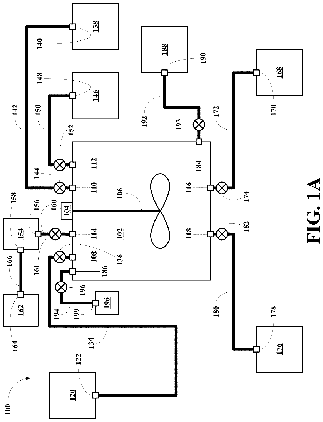
[0045]Referring now to FIG. 1A, a first embodiment of system of this invention, generally 100, is shown to include a heated reaction vessel 102 including a motor 104 and a paddle stirrer 106. The reaction vessel 102 also includes a REM containing magnet material inlet 108, a water inlet 110 and a formic acid inlet 112. The reaction vessel 102 also includes a gas outlet 114, a waste liquid outlet 116 and a REM product outlet 118.

[0046]The system 100 also includes a REM containing magnet material source vessel 120 having a REM containing magnet material outlet 122. The outlet 122 is connected to the inlet 108 via a REM containing magnet material conduit 134 having a REM containing magnet material conduit valve 136.

[0047]The system 100 also includes a water source vessel 138 having a water outlet 140. The water outlet 140 is connected to the water inlet 110 via a water conduit 142 having a water conduit valve 144. The system 100 also includes a formic acid source vessel 146 having a fo...

second embodiment

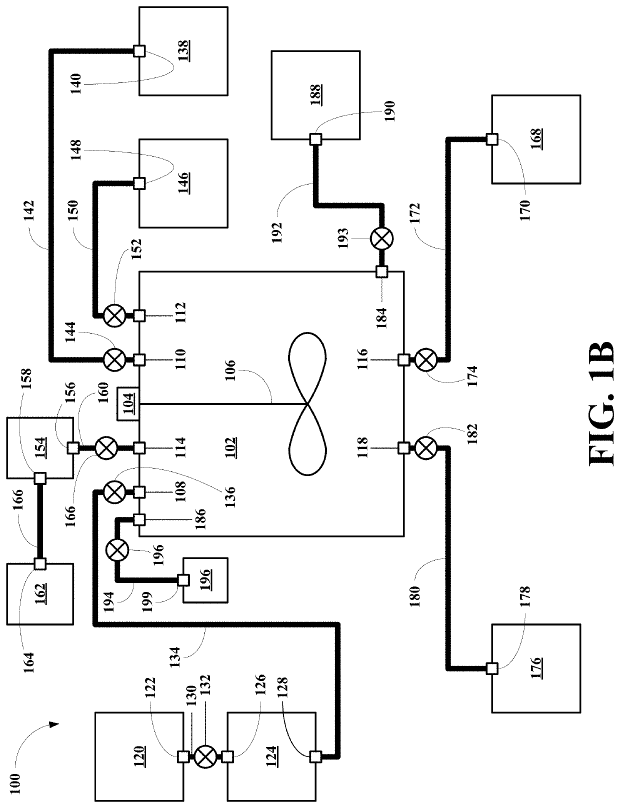
[0052]Referring now to FIG. 1B, a first embodiment of system of this invention, generally 100, is shown to include a heated reaction vessel 102 including a motor 104 and a paddle stirrer 106. The reaction vessel 102 also includes a particulate REM containing magnet material inlet 108, a water inlet 110 and a formic acid inlet 112. The reaction vessel 102 also includes a gas outlet 114, a waste liquid outlet 116 and a REM product outlet 118.

[0053]The system 100 also includes a REM containing magnet material source vessel 120 having a REM containing magnet material outlet 122. The system 100 also includes a commutating unit 124 having a REM containing magnet material inlet 126 and a particulate REM containing magnet material outlet 128. The REM containing magnet material outlet 122 is connected to the magnet inlet 126 via a magnet conduit 130 having a magnet conduit valve 132. The particulate magnet outlet 128 is connected to the particulate magnet inlet 108 via a particulate magnet c...

third embodiment

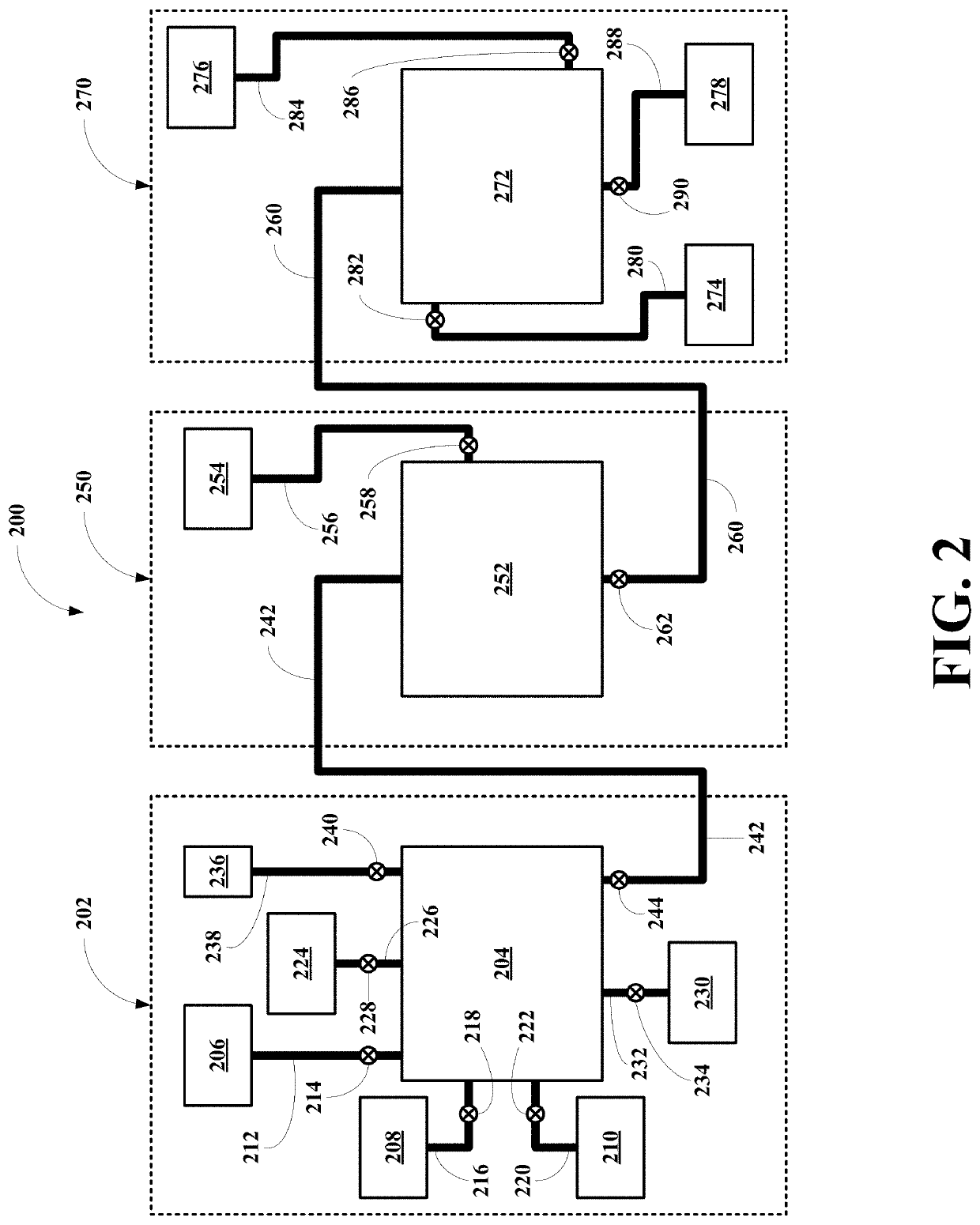
[0059]Referring now to FIG. 2, a first embodiment of system of this invention, generally 200, is shown to include a reaction subsystem 202, a separation subsystem 250, and an extraction subsystem 270.

[0060]Reaction Subsystem

[0061]The reaction subsystem 202 includes a single reaction vessel 204, a REM containing magnet material source vessel 206, a formic acid source vessel 208, and a water source vessel 210. The magnet material source vessel 206 is connected to the reaction vessel 204 via a magnet material conduit 212 having a magnet material valve 214. The formic acid source vessel 208 is connected to the reaction vessel 204 via a formic aid conduit 216 having a formic acid valve 218. The water source vessel 210 is connected to the reaction vessel 204 via a water conduit 220 having a water valve 222. The reaction vessel 204 also includes a hydrogen gas utilization unit 224 connected to the reaction vessel 204 via a hydrogen gas conduit 226 having a hydrogen gas valve 228. The react...


PUM

PropertyMeasurementUnit
temperatureaaaaaaaaaa
pressureaaaaaaaaaa

Abstract

Systems and methods for recovering rare earth metals from rare earth metal-containing magnets includes fragmenting or commutating the magnets, contacting the commutated magnets with a mixture of low molecular weight carboxylic acids such as formic acid and water, and removing or extracting non-rare earth metal carboxylate phases such as an iron carboxylate (formate) phase from a rare earth metal carboxylate (formate) phase, using a solvent such as water.

Description

RELATED APPLICATIONS[0001]This application is a 35 U.S.C. § 371 United States National Phase Patent Application of PCT / US16 / 41792 filed 11 Jul. 2016, which claims priority to and the benefit of U.S. Provisional Patent Application Ser. No. 62 / 191,238, filed Jul. 10, 2015 (10 Jul. 2015).BACKGROUND OF THE INVENTION1. Field of the Invention[0002]Embodiments of the present invention relate to systems and methods for recycling rare earth elements from end-of use products containing rare earth magnets.[0003]More particularly, embodiments of this invention relates to systems and methods for recycling rare earth elements from end-of use products containing rare earth magnets, especially neodymium-iron-boron (NdFeB) magnets, where the methods include the steps of optionally fragmenting or commutating the magnets, contacting the commutated magnets with a mixture of formic acid and water to form rare earth metal (REM) formate precipitates (REM(HCOO)3), separating the filtrate, which is impregna...

Claims


Application Information

Patent Timeline
Patent Type & Authority Patents(United States)
IPC IPC(8): C22B59/00C22B7/00C22B1/00C22B3/02C07F5/00H01F41/02
CPCC07F5/003C22B1/005H01F41/0253C22B7/007C22B3/02C22B59/00Y02P10/216Y02P10/234Y02P10/20
Inventor JACOBSON, ALLAN J.SAMARASEKERE, PRADEEP
Owner UNIV HOUSTON SYST
Why Eureka
Try Eureka