Capacitive switch device

a technology of capacitive switch and capacitive film, which is applied in the direction of electronic switching, electrical equipment, pulse technique, etc., can solve the problems of expanding film not being restored to its original size, causing creases in the film, and causing lifting

Active Publication Date: 2020-03-10
DENSO CORP
View PDF10 Cites 0 Cited by
  • Summary
  • Abstract
  • Description
  • Claims
  • Application Information

AI Technical Summary

Benefits of technology

[0009]In view of the foregoing inconveniences, an object of the present disclosure is to provide a capacitive switch device capable of restricting an occurrence of lifting of a film in response to a temperature change.
[0012]Owing to the configuration as above, when the film member undergoes a temperature change, the film member is allowed to thermally expand and thermally contract independently from the operation panel in the second portion while the first portion is bonded to the operation panel. Hence, creases formed due to a difference in expansion and contraction between the operation panel and the film member can be eliminated. Consequently, an occurrence of lifting of the film member in response to a temperature change can be eliminated.

Problems solved by technology

However, when the film is bonded partially, the operation panel and the film may expand and contract differently in response to a temperature change due to a difference in linear expansion coefficient and a difference in glass transition point (Tg point), and corrugated creases may be generated in the film, for example, and lifting may occur between the operation panel and the film.
Thus, the expanded film is not restored to an original size.
In such a case, the film may become slack like corrugated creases and lifting may occur.
When such lifting occurs, a distance between the operation panel and the electrode portion may vary and sensitivity of the electrode portion is likely to deteriorate.

Method used


Image

  • Capacitive switch device
  • Capacitive switch device
  • Capacitive switch device

Examples


first embodiment

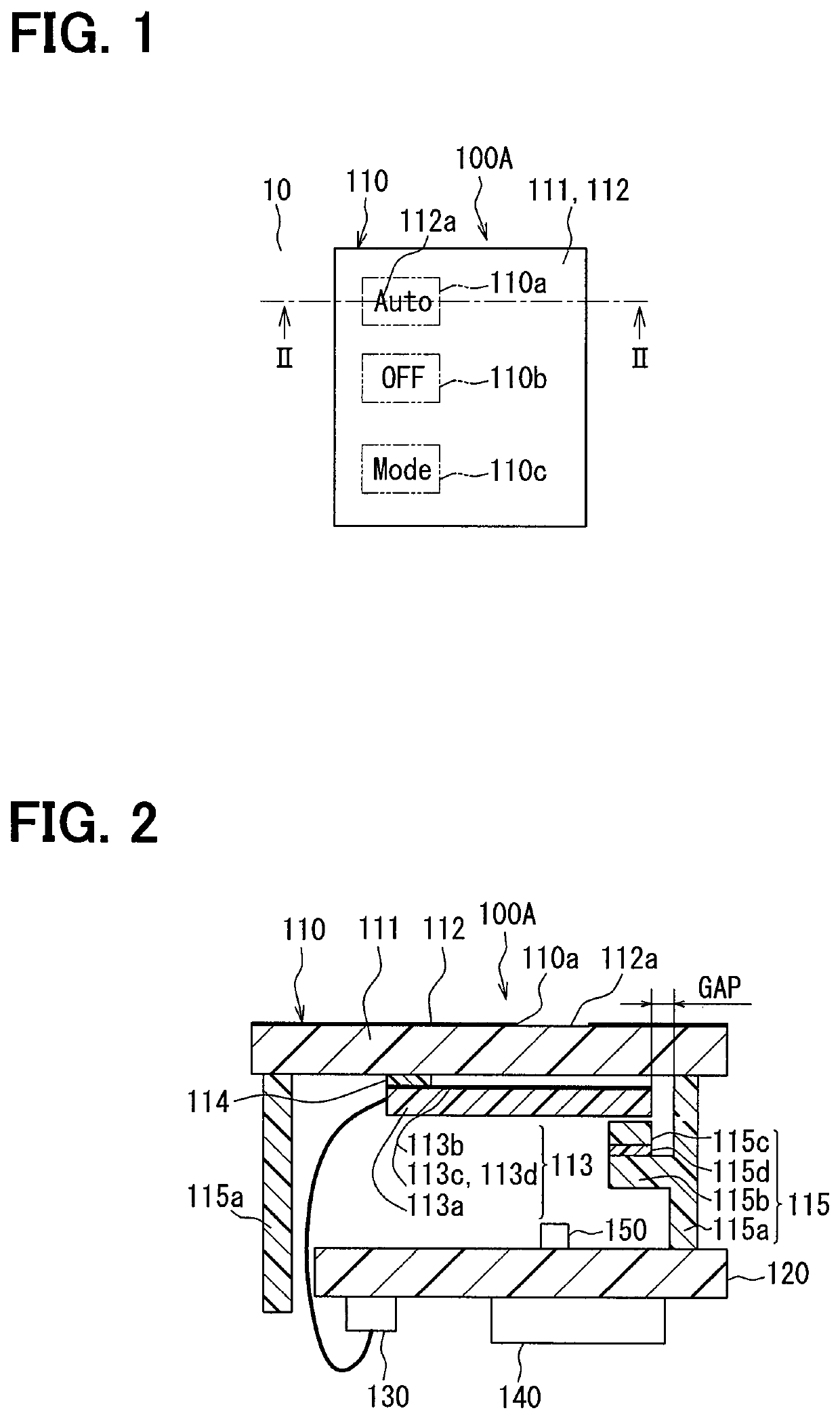
[0024]A first embodiment of the present disclosure will be described using FIG. 1 through FIG. 3. A capacitive switch device (hereinafter, referred to simply as the switch device) 100A of the present embodiment is used to input an operating condition into an air-conditioning device as an example of a predetermined device equipped to a vehicle. The switch device 100A includes an input portion 110, a substrate 120, a connector 130, a detection IC 140, an illumination LED 150, and so on.

[0025]The input portion 110 is a portion through which a driver (user) inputs an operating condition into the air-conditioning device by an operation with a finger. The input portion 110 is located at an easy-to-operate position for the driver in an instrument panel 10 of the vehicle. Phrases, “a finger operation” and “operation or operated with a finger”, referred to herein mean an operation to touch any one of switches 110a through 110c described below with a finger, which corresponds to a touch opera...

second embodiment

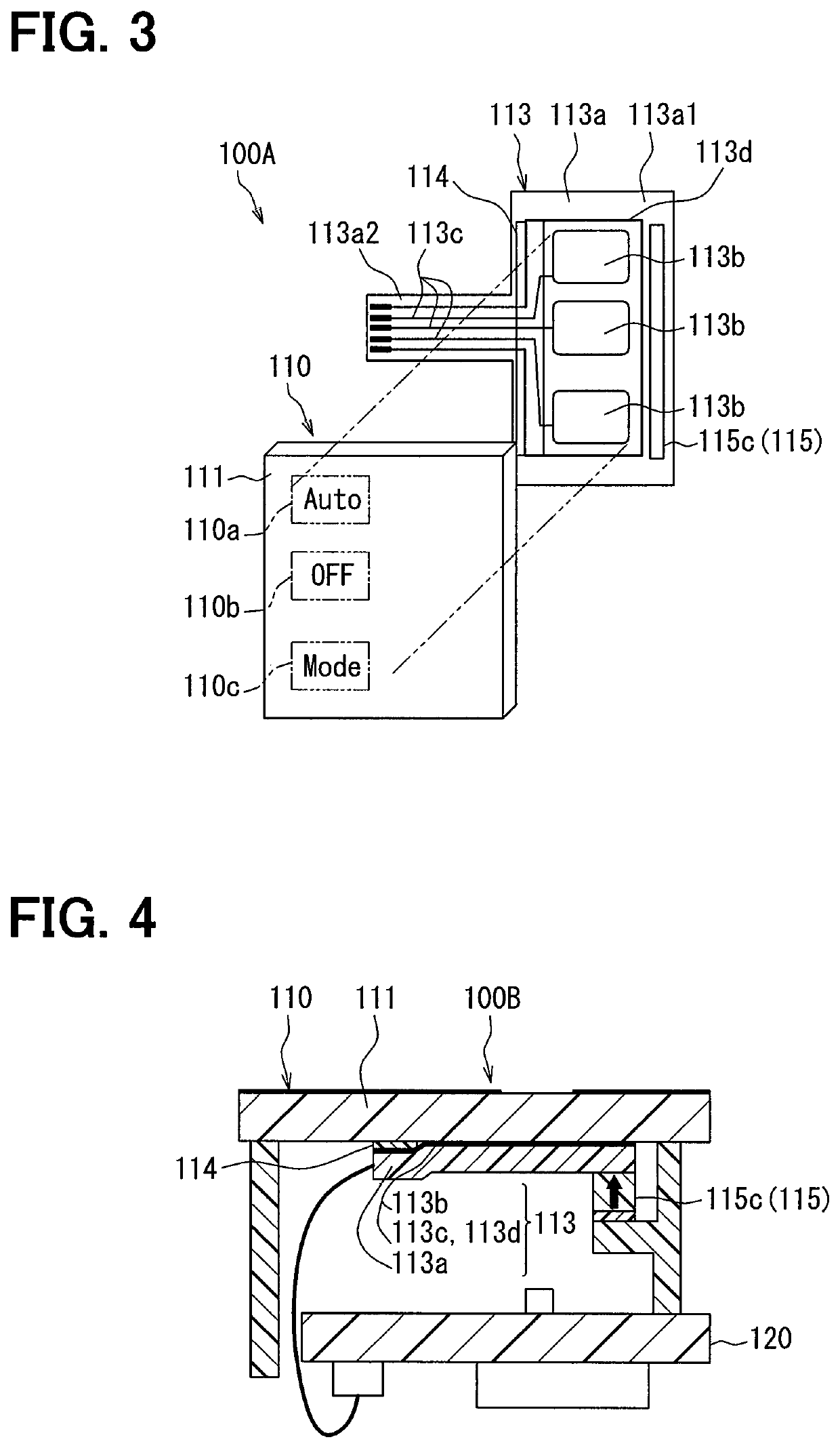
[0051]A switch device 100B of a second embodiment is shown in FIG. 4. The switch device 100B of the second embodiment is different from the switch device 100A of the first embodiment above in that a soft member 115c pushes an other-end portion of a base film 113a toward an operation panel 111. An arrow of FIG. 4 indicates a pushing direction.

[0052]A tip-end surface of the soft member 115c is in contact with a surface of the base film 113a on a side of a substrate 120 and applies a predetermined pushing force to the base film 113a toward the operation panel 111. No gap or a fine gap is provided between the operation panel 111 and an electrode portion 113b and the base film 113a is maintained in a posture along surfaces of the operation panel 111. Even under a pushing force applied by the soft member 115c, the base film 113a is allowed to move due to thermal expansion and thermal contraction in an in-plane direction of the base film 113a in a same manner as in the first embodiment abo...

third embodiment

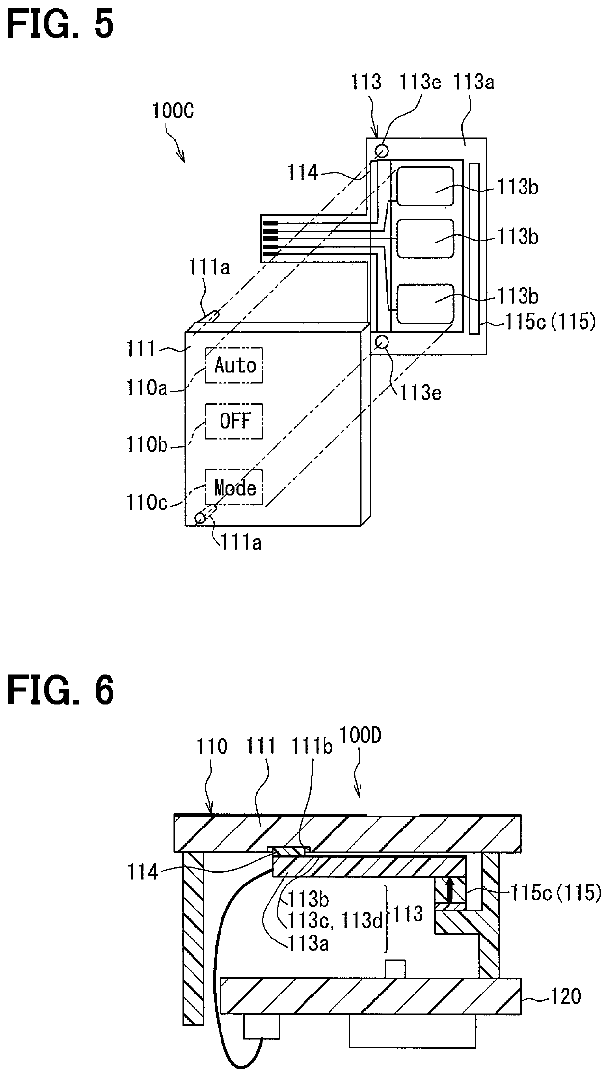
[0055]A switch device 100C of a third embodiment is shown in FIG. 5. The switch device 100C of the third embodiment is different from the switch devices 100A and 100B of the first and second embodiments above in that a positioning portion which fixes a position of a base film 113a with respect to an operation panel 111 is additionally provided.

[0056]The positioning portion is provided to the operation panel 111 and has a rod-shaped positioning pin 111a extending toward the base film 113a and a positioning hole 113e provided to the base film 113a to let the positioning pin 111a pass through.

[0057]The positioning pin 111a and the positioning hole 113e are provided to correspond to a region where a double-faced adhesive tape 114 is provided. More specifically, the positioning pin 111a and the positioning hole 113e are provided in portions (two portions) located at both ends of the double-faced adhesive tape 114 in a longitudinal direction.

[0058]Owing to the configuration as above, the ...


PUM


Abstract

A capacitive switch device includes an operation panel operated by a user with a touch operation, a film member provided along a surface of the operation panel on an opposite side from a surface operated with the touch operation, and an electrode portion forming a capacitor with a finger of the user and a wiring portion, both the electrode portion and the wiring portion being provided to the film member. The film member is bonded to the operation panel by a pressure-sensitive adhesive at a predetermined first portion of the film member and supported at a second portion of the film member different from the first portion by a supporting portion which allows the film member to move due to thermal expansion and thermal contraction in an in-plane direction of the film member.

Description

CROSS REFERENCE TO RELATED APPLICATION[0001]This application is a U.S. National Phase Application under 35 U.S.C. 371 of International Application No. PCT / JP2016 / 002096 filed on Apr. 19, 2016 and published in Japanese as WO 2016 / 185669 A1 on Nov. 24, 2016. This application is based on and claims the benefit of priority from Japanese Patent Application No. 2015-102039 filed on May 19, 2015. The entire disclosures of all of the above applications are incorporated herein by reference.TECHNICAL FIELD[0002]The present disclosure relates to a capacitive switch device through which an operating condition is inputted into a predetermined device by a user with a touch operation.BACKGROUND ART[0003]A capacitive switch device in the related art is described in, for example, Patent Literature 1. A switch device of Patent Literature 1 includes a plate-shaped operation panel (dielectric material) operated by a user with a finger, and a film (PET film) provided with an electrode portion (switch el...

Claims


Application Information

Patent Timeline
Patent Type & Authority Patents(United States)
IPC IPC(8): H03K17/96
CPCH03K17/9622H03K17/962H03K2217/96079H03K2217/960755
Inventor ITOH, MASAHIRO
Owner DENSO CORP
Why Eureka
Try Eureka