
Frequency adjustable pre-matching coaxial transistor test fixture

a coaxial transistor and test fixture technology, applied in the direction of individual semiconductor device testing, instruments, base element modifications, etc., can solve the problems of extremely low loss test fixtures and reduced tuning range of tuners, and achieve non-negligible insertion loss, low input and output impedance, and low cost

Active Publication Date: 2020-03-17
TSIRONIS CHRISTOS
View PDF2 Cites 1 Cited by
  • Summary
  • Abstract
  • Description
  • Claims
  • Application Information

AI Technical Summary

Benefits of technology

Enables efficient impedance matching and frequency adjustment without physical replacement, reducing insertion loss and expanding the tuning range for high power high frequency transistors, while maintaining secure attachment and RF safety.

Problems solved by technology

However the tuning range of the tuners is reduced by the insertion loss of the test fixtures; therefore the requirement for extremely low loss test fixtures.

Method used


Image

  • Frequency adjustable pre-matching coaxial transistor test fixture
  • Frequency adjustable pre-matching coaxial transistor test fixture
  • Frequency adjustable pre-matching coaxial transistor test fixture

Examples


Embodiment Construction

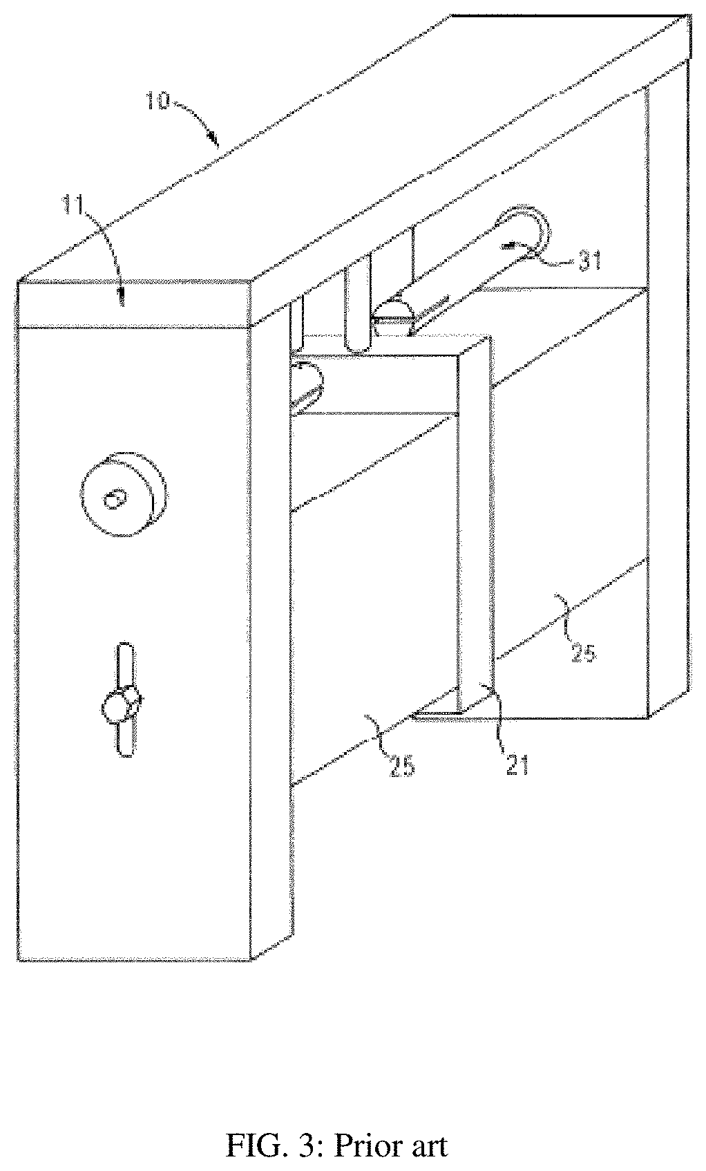
[0022]FIGS. 3 and 4 show the prior art coaxial transistor test fixture (see ref. 1 and 4). Two coaxial connectors (40, 42) are attached to vertical walls (413, 414) and the extensions of the center conductors (31, 47, 48) of the connectors form with the two blocks (25, 49) and the metallic cover (11, 46) form an open transmission line (slabline), which is interrupted in the center to insert a block (21, 44, 410), referred to hitherto as “INSERT”, which carries the packaged DUT (43). In this case the transistor package (43, 45) is firmly secured on the INSERT (44) which is part of the horizontal slabline structure. The signal enters in the input port (40) and leaves at the output port (42) and is conducted to the transistor by the two coaxial center conductor segments (47, 48). The transistor leads (41) are inserted into horizontal slots (411) of the center conductors. The test fixture INSERT (44, 410) holds the transistor package (43, 45) with two screws (412) for good RF grounding ...


PUM

PropertyMeasurementUnit
impedanceaaaaaaaaaa
internal impedanceaaaaaaaaaa

Abstract

Coaxial microwave transistor test fixtures provide lowest insertion loss possible and include, as part of the input and output sections, transformer networks in form of single stage λ / 4 segments bringing (pre-matching) the system 50Ω load closer to the conjugate internal impedance of power transistors. The transforming networks are flat, cylindrical or have oval or elliptical cross sections and have adjustable length, thus operating optimally for transistors with varying optimum frequency and internal impedance and / or capacitive or inductive impedance part. The change in length is done without affecting the overall fixture geometry and structure. The fixtures can be calibrated using standard TRL method.

Description

PRIORITY CLAIM[0001]This application claims priority on provisional application 62 / 436,755, titled: Frequency Adjustable Coaxial Transistor Test Fixture, filed on Dec. 20, 2016.CROSS-REFERENCE TO RELATED ARTICLES[0002]1. TSIRONIS, U.S. Pat. No. 6,414,563, “Low-Loss Microwave Device Test Fixture with Adjustable Blocks”.[0003]2. “Test Fixture for Medium and High Power RF Transistors”, Product Note 7, Focus Microwaves, January 1994.[0004]3. “Load Pull”, [online], Wikipedia [Retrieved on Nov. 18, 2016] Retrieved from Internet <URL: http: / / en.wikipedia.org / wiki / Load_pull>.[0005]4. “MLTF, a Minimum Loss Transistor Test Fixture”, Product Note 54, Focus Microwaves, 1999.BACKGROUND OF THE INVENTION[0006]This invention relates to high frequency transistor test fixtures used in testing RF transistors in microwave frequencies (see ref. 1, 2). Active RF components (transistors—DUT) need to be thoroughly tested at the operation frequencies before used in amplifier and other circuit designs....

Claims


Application Information

Patent Timeline
Patent Type & Authority Patents(United States)
IPC IPC(8): G01R1/04G01R31/26G01R1/20
CPCG01R1/203G01R31/2601G01R1/0408C12Q1/02C12Q1/18C12Q1/10C12Q1/6897G01N2333/24
Inventor TSIRONIS, CHRISTOS
Owner TSIRONIS CHRISTOS
Learn More