Terminal fitting for coaxial connector

a technology of coaxial connectors and fittings, applied in the field of fittings, can solve the problems of reducing high frequency performance and affecting the flow of current, and achieve the effects of improving high frequency performance, improving characteristic impedance, and improving assembly efficiency

Active Publication Date: 2020-03-17
SUMITOMO WIRING SYST LTD
View PDF11 Cites 11 Cited by
  • Summary
  • Abstract
  • Description
  • Claims
  • Application Information

AI Technical Summary

Benefits of technology

[0009]According to the invention, the inner conductor can be connected to the shielded cable, for example, by inserting a tool for the center conductor crimping portion into the opening and performing an operation of the crimping the center conductor crimping portion in that state after the inner conductor is assembled with the outer conductor. Thus, assembling efficiency can be improved. On the other hand, if an opening is present in the outer conductor, the flow of a current may be impeded. In that respect, the cover is provided to close the opening and electrically contact the outer conductor in the case of the invention. Thus, a smooth flow of a shield current can be ensured through the cover and high frequency performance can be improved.
[0010]The inner conductor may include a deflectable resilient piece configured to resiliently contact a mating terminal fitting. The resilient piece may be exposed on an outer surface of the inner conductor, and the outer conductor may include a tubular portion configured to surround the resilient piece. If the deflectable resilient piece is exposed on the outer surface of the inner conductor in this way, it is desired to transport the terminal fitting in a state where the resilient piece is protected to a work site or the like where a crimping operation is performed. In that respect, according to the above configuration, the terminal fitting can be transported in a state where the outer conductor is assembled with the inner conductor and the tubular portion surrounds the resilient piece, and the operation of crimping the center conductor crimping portion can be performed through the opening at the work site. As a result, the resilient piece can be kept protected. Further, the inner conductor is not provided with an outer tube for surrounding the resilient piece. Thus, external dimension differences between the inner conductor and the mating terminal fitting can be suppressed to be small and a characteristic impedance can be improved.
[0011]In the above configuration, the cover may electrically contact the shield crimping portion and the tubular portion. Accordingly, a good current path extendable straight through the cover can be secured and high frequency performance can be improved.
[0012]The cover may include a surrounding portion configured to surround the shield crimping portion along an outer periphery of the shield crimping portion. According to this configuration, the shield crimping portion can be prevented from inadvertently expanding.

Problems solved by technology

Thus, high frequency performance is reduced.
On the other hand, if an opening is present in the outer conductor, the flow of a current may be impeded.
Further, the inner conductor is not provided with an outer tube for surrounding the resilient piece.

Method used


Image

  • Terminal fitting for coaxial connector
  • Terminal fitting for coaxial connector
  • Terminal fitting for coaxial connector

Examples


Embodiment Construction

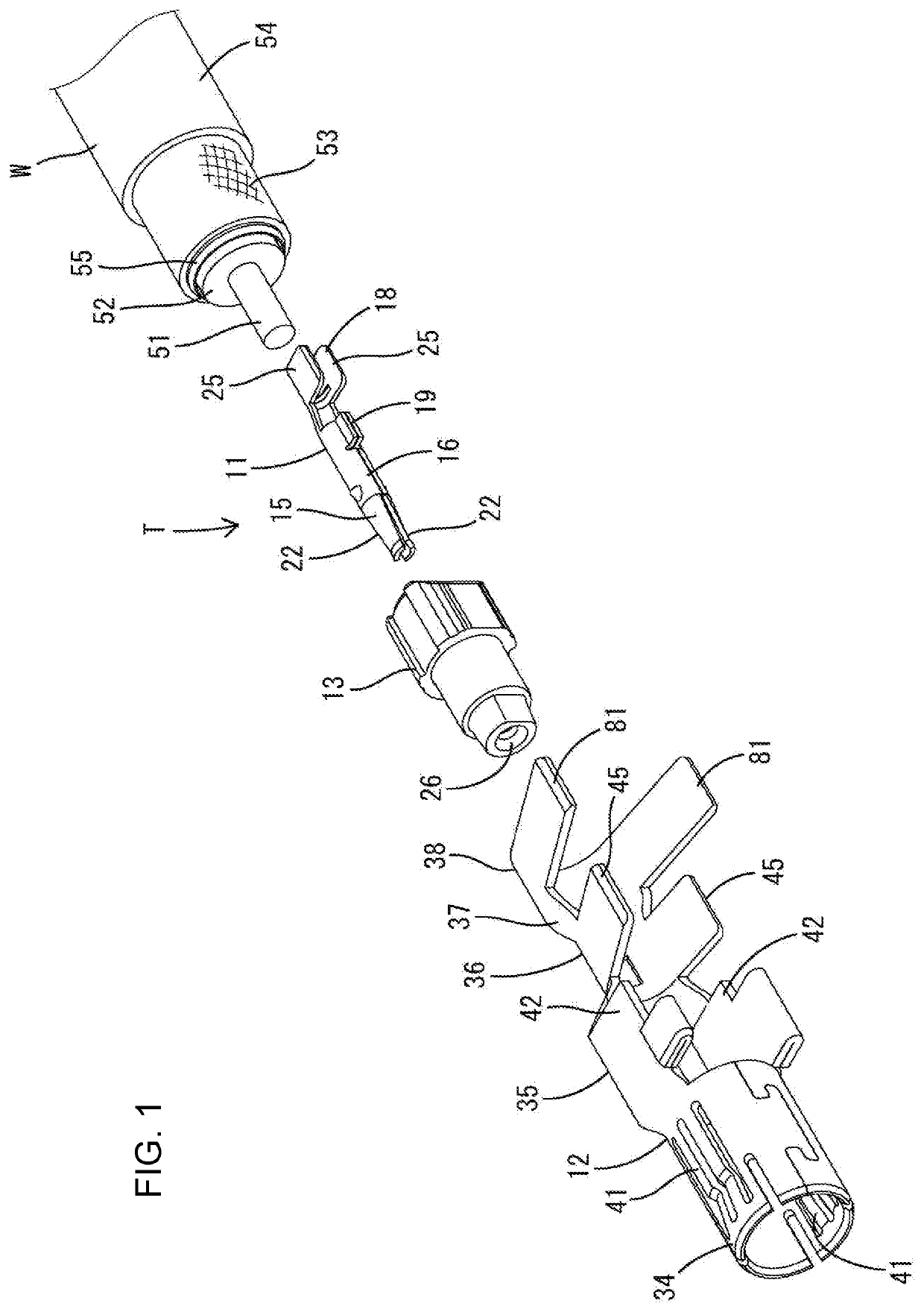
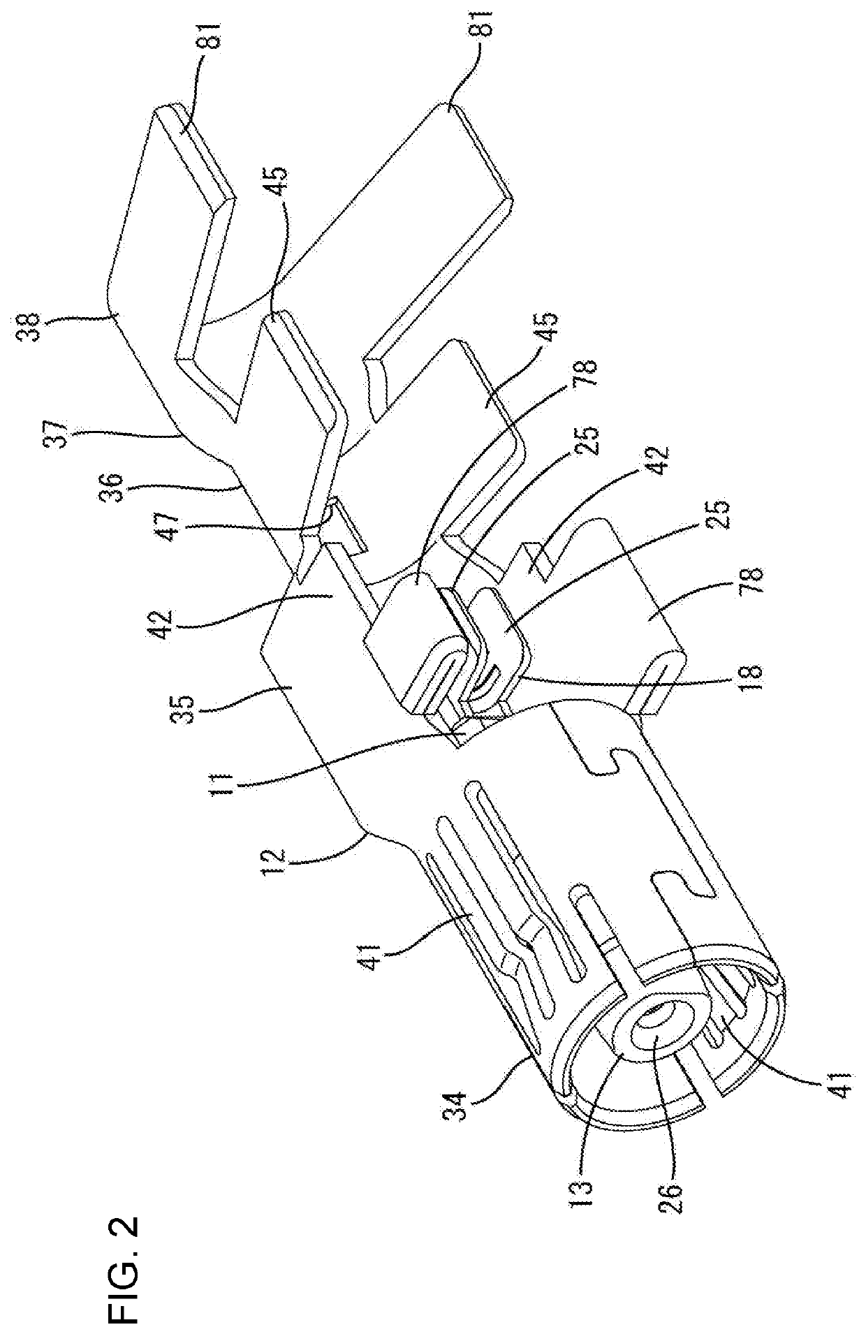
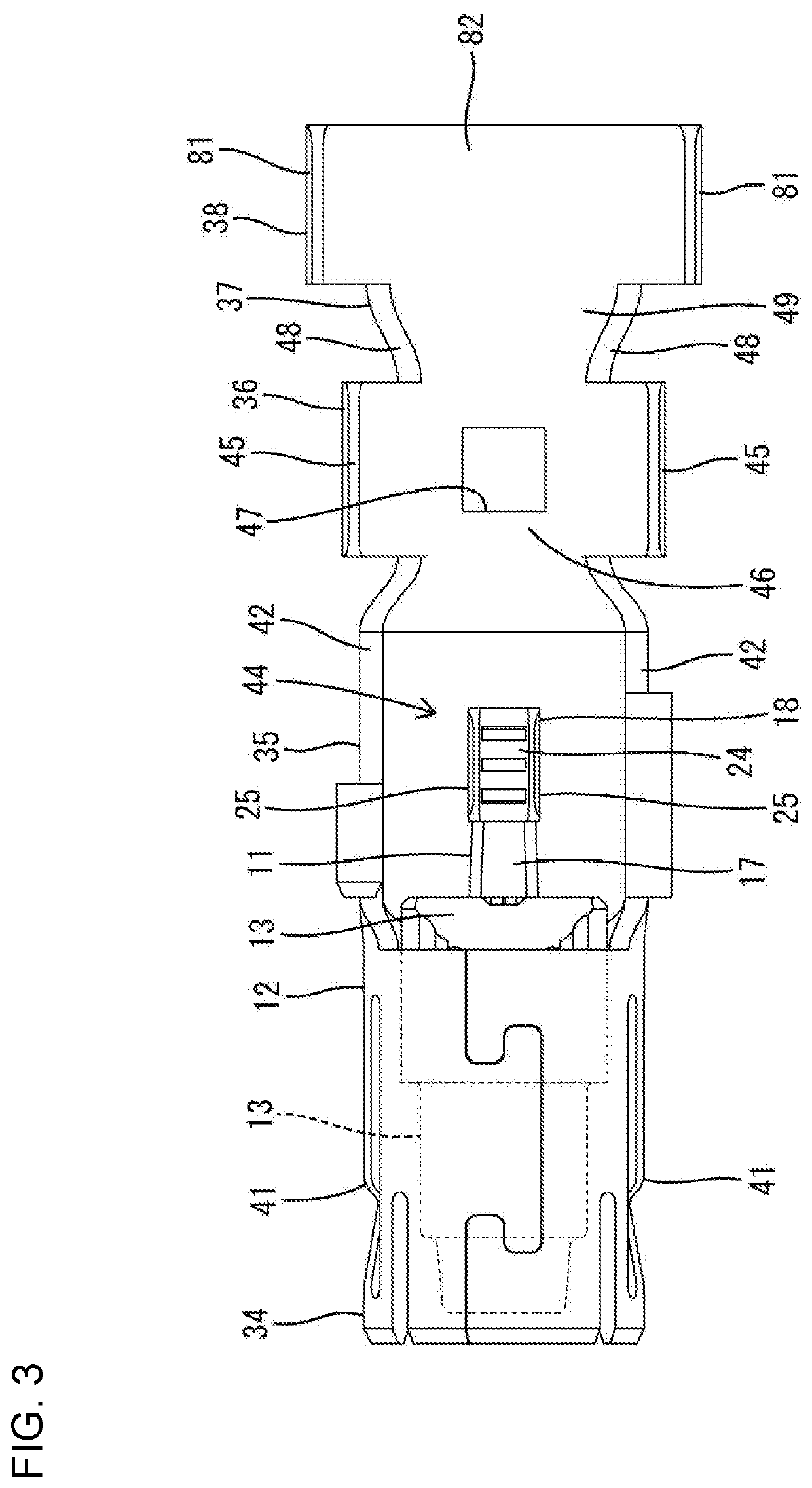
[0033]An embodiment is described with reference to the drawings. A terminal fitting T according to this embodiment is connected to an end part of a shielded cable W and includes, as shown in FIG. 1, an inner conductor 11, an outer conductor 12, a dielectric 13 and a cover 14. The inner conductor 11, the outer conductor 12 and the cover 14 are made of a conductive metal, and the dielectric 13 is made of an insulating synthetic resin. This terminal fitting T is connected electrically to a mating terminal fitting 60 from the front.

[0034]As shown in FIG. 1, the shielded cable W is a so-called coaxial cable and includes a conductive core 51 (center conductor) formed by twisting a plurality of strands, an insulating coating 52 surrounding the outer periphery of the core 51, a conductive braided wire 53 (shield layer) formed by weaving strands into a net that surrounds the outer periphery of the coating 52 and an insulating sheath 54 surrounding the outer periphery of the braided wire 53. ...


PUM


Abstract

A terminal fitting (T) includes an inner conductor (11) having a center conductor crimping portion (18) to be crimped to a center conductor of a shielded cable (W) and an outer conductor (12) having a coupling (35). The center conductor crimping portion (18) is disposed inside the coupling by assembling the inner conductor (11). Openings (43, 44) open in the coupling (35) and enable tools to be applied to the center conductor crimping portion. A shield crimping portion (36) is connected to the coupling (35) and to be crimped to a shield layer of the shielded cable W. A dielectric (13) is interposed between the outer and inner conductors (12, 11), and a cover (14) is configured to close the openings (43, 44) and electrically contact the outer conductor (12). The cover (14) has locking pieces (96) that are to be bent and locked into a locking hole (47) of the shield crimping portion (36).

Description

BACKGROUND[0001]Field of the Invention[0002]The invention relates to a terminal fitting.[0003]Related Art[0004]A high-frequency compatible shielded cable is routed in an automotive vehicle to transmit a high-frequency signal to a circuit board of an electrical device, such as a television or car navigation system mounted in the vehicle. Japanese Utility Model No. 2606411 discloses a shielded cable known as a hollow cable. The hollow cable is connected to an electrical contact terminal that includes a shielding outer tube. The shielding outer tube includes a contact holding portion and an outer conductor crimping portion behind the contact holding portion. A tool insertion opening vertically penetrates through the contact holding portion. A center conductor contact is accommodated in the shielding outer tube via an insulator and includes a center conductor crimping portion.[0005]A center conductor exposed on a tip of the hollow cable is placed on the center conductor crimping portion...

Claims


Application Information

Patent Timeline
Patent Type & Authority Patents(United States)
IPC IPC(8): H01R9/05H01R13/6583H01R13/11H01R43/16H01R4/20H01R4/18H01R103/00
CPCH01R43/16H01R13/113H01R13/6583H01R9/0518H01R4/20H01R2103/00H01R4/184H01R4/185H01R24/40
Inventor KANEMURA, KEISUKEMITSUI, SHOHEINAKANISHI, YUICHIHIRANO, AI
Owner SUMITOMO WIRING SYST LTD
Why Eureka
Try Eureka