Circuit for regulating leakage current in charge pump

a charge pump and leakage current technology, applied in the field of semiconductor technology, can solve the problems that the leakage current cannot now regulate the output voltage well, and the program/erase operation of the cell still requires relatively high voltage, so as to achieve the effect of higher output voltage of the charge pump, reduced fluctuations, and strong output ability

Active Publication Date: 2020-03-31
WUHAN XINXIN SEMICON MFG CO LTD
View PDF6 Cites 2 Cited by
  • Summary
  • Abstract
  • Description
  • Claims
  • Application Information

AI Technical Summary

Benefits of technology

[0007]It is an object of the present invention to provide a circuit for regulating a leakage current in a charge pump so as to overcome the problem with conventional charge pumps that a widely varying supply voltage will weaken the regulating ability of a leakage current in the charge pump.
[0040]In the circuit of the present invention, the current flowing through the source and drain of the first transistor (which is a leakage current) is proportional to the supply voltage. When the supply voltage VCC is at a higher level, the charge pump will have a stronger output ability. As a result, more electric charges will be present at its output, creating a higher output voltage of the charge pump. However, as the leakage current increases with the supply voltage, the higher level of the supply voltage will also lead to drainage of more electric charges from the output of the charge pump. As a result, the output voltage of the charge pump will experience smaller fluctuations and allow regulation of the output voltage in a large extent such that an output power of the charge pump is reduced. On contrary, when the supply voltage VCC is at a lower level, the output ability of the charge pump will be weaker. Therefore, fewer electric charges will be present at the output of the charge pump, resulting in a lower output voltage thereof. At the same time, the leakage current will be lower at a lower level of the supply voltage, which will lead to drainage of fewer electric charges from the output of the charge pump. As a result, the output voltage of the charge pump will also experience smaller fluctuations. As such, fluctuations in the output voltage can be controlled within a narrow range, regardless of whether the supply voltage is high or low.

Problems solved by technology

On the other hand, in flash memories, program / erase operations of a cell still require relatively high voltages.
However, when the charge pump is powered with a supply voltage varying in a wide range, the leakage current would no longer be able to regulate the output voltage well.

Method used


Image

  • Circuit for regulating leakage current in charge pump

Examples


Embodiment Construction

[0043]The present invention will be described below in further detail with reference to the accompanying drawings and some specific embodiments. Features and advantages of the invention will be more apparent from the following detailed description, and from the appended claims. It is noted that the figures are provided in a very simplified form not necessarily presented to scale, with the only intention to facilitate convenience and clarity in explaining the embodiments of the invention.

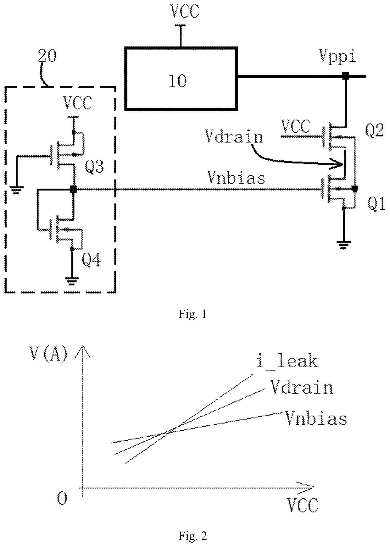
[0044]The core concept of the present invention is to provide a circuit for regulating a leakage current in a charge pump so as to overcome the problem with conventional charge pumps that a widely varying supply voltage will weaken the regulating ability of a leakage current in the charge pump.

[0045]To this end, the present invention provides a circuit for regulating a leakage current in a charge pump, comprising a bias voltage generating circuit and a first transistor. The bias voltage generating ci...


PUM


Abstract

A circuit for regulating a leakage current in a charge pump is disclosed. The circuit includes a bias voltage generating circuit and a first transistor, wherein: the bias voltage generating circuit generates a bias voltage that is proportional to a supply voltage; a gate of the first transistor is coupled to the bias voltage; the first transistor has a drain that is coupled to an output of the charge pump and a source that is grounded; a voltage the drain of the first transistor is proportional to the supply voltage; and a current flowing through the source and drain of the first transistor is proportional to the supply voltage that powers the charge pump.

Description

CROSS-REFERENCES TO RELATED APPLICATION[0001]This application claims the priority of Chinese patent application number 201810327017.6, filed on Apr. 12, 2018, the entire contents of which are incorporated herein by reference.TECHNICAL FIELD[0002]The present invention relates to the field of semiconductor technology and, in particular, to a circuit for regulating a leakage current in a charge pump.BACKGROUND[0003]A charge pump circuit is a basic block for a flash memory and greatly affects the flash memory's program / erase speed. The continuous advancement of integrated circuit (IC) fabrication technology and our relentless pursuit for lower power consumption lead to the development of ICs powered by increasingly lower supply voltages.[0004]On the other hand, in flash memories, program / erase operations of a cell still require relatively high voltages. In such a context, more and more importance is being attached to charge pump circuits in the continuously-developing IC domain. Current...

Claims


Application Information

Patent Timeline
Patent Type & Authority Patents(United States)
IPC IPC(8): G05F3/02H02M3/07G11C16/30G11C16/14G05F3/20
CPCG05F3/02G11C16/30H02M3/07G05F3/205G11C16/14G11C5/146H02M1/14G11C5/145
Inventor TANG, YUANSHENG, BINCHA, BYOUNG KWONXU, YIHSU, JEN-TAI
Owner WUHAN XINXIN SEMICON MFG CO LTD
Why Eureka
Try Eureka