Dental system

a technology of dental system and straight handpiece, applied in the field of medical or dental system, can solve the problems of electrical signals, in particular data, between the straight handpiece and the straight handpi

Active Publication Date: 2020-04-07
W&H DENTALWERK
View PDF45 Cites 2 Cited by
  • Summary
  • Abstract
  • Description
  • Claims
  • Application Information

AI Technical Summary

Benefits of technology

[0016]It is thus an object to create a medical or dental system which makes it possible to ensure the secure transmission of electrical signals and / or data between a first transmitting and / or receiving unit and a second transmitting and / or receiving unit. In particular, it is an object of the invention to guarantee the secure transmission of electrical signals even when the components of the medical system are not connected directly with one another.
[0021]Furthermore, the at least one first transmitting and / or receiving unit and / or the at least one second transmitting and / or receiving unit are each disposed in a housing, the housing being designed in such a way that the functionality of the first or second transmitting and / or receiving unit disposed in the housing can be maintained even after multiple cleaning, care, and / or sterilization processes. The housing preferably is made of a magnetic and electrically non-conductive material, in particular of plastic, glass, or ceramic, and comprises a holding device, in particular a thread, a clip, a clamp, and / or another form of retaining element, so that the at least one first transmitting and / or receiving unit and / or the at least one second transmitting and / or receiving unit can be disconnected from the medical system.
[0029]Furthermore, the medical, in particular dental system can ensure the secure transmission of signals and / or data between the at least one first transmitting and / or receiving unit and the at least one second transmitting and / or receiving unit even when the at least two transmitting and / or receiving units of the medical system are not coupled directly to one another. The use of the human body of the user and / or of the person to be treated as an electrical path for the transmission of electrical signals and / or data prevents the risk of endangering the signal and / or data transfer. In the case of an inductive energy and / or data transfer, as is known from the prior art, the signal and / or data transfer can be disturbed by electrical counterfields generated by metallic components in the vicinity of the transmitting and / or receiving coils.

Problems solved by technology

A disadvantage of this configuration of the medical system is the transmission of electrical signals, in particular data, between the straight handpiece or contra-angled handpiece and the supply unit and / or the processing device.
But also when using transponders for wireless transmission, which have transmitting and / or receiving coils for the transmitting and / or receiving of signals, coupling of both coupling parts is required, because of the low transmitting and / or receiving power of the coils due to the small size of the transmitting and / or receiving coils and because of the metallic materials in the components of the medical system, in particular in their coupling parts.

Method used


Image

  • Dental system
  • Dental system
  • Dental system

Examples


first embodiment

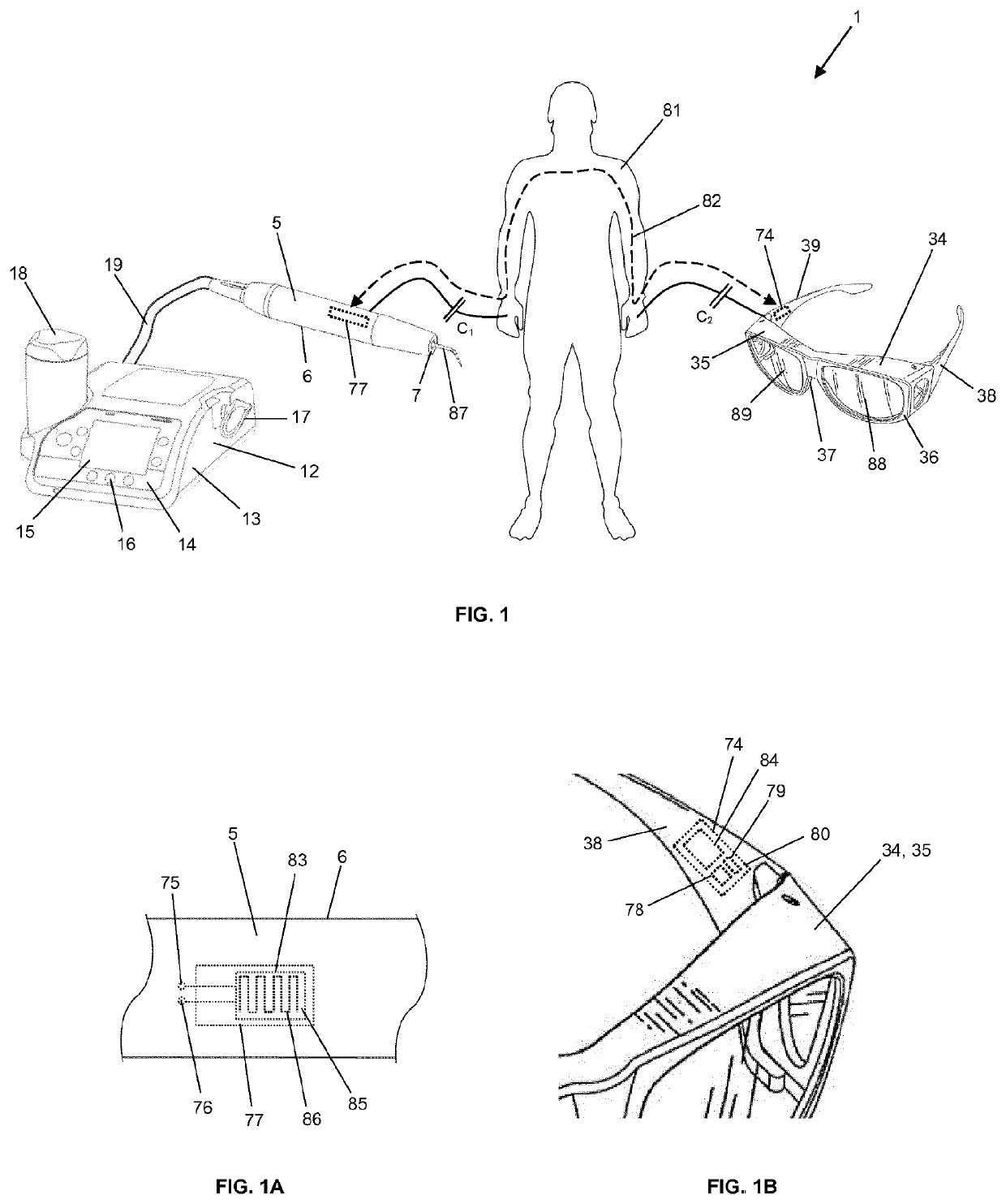
[0037]the medical or dental system 1, shown in FIG. 1, comprises a drive unit and / or control unit 12 with a medical, in particular a dental handpiece 5 and an accessory 34 designed for the operation with the handpiece 5. The accessory in this case is constructed as glasses 34, in particular filter glasses for the detection of an anomaly on a tooth.

[0038]The drive unit and / or control unit 12 comprises a housing 13 with a handpiece holder 17. On the front, the drive unit and / or control unit 12 has an operating unit 14. This is formed by a display 15 with a plurality of operating elements 16 for displaying and adjusting the operating parameters of the drive unit and / or control unit 12 and / or of the medical handpiece 5. Furthermore, the drive unit and / or control unit 12 has a fluid tank 18. Finally, in order to drive, control and / or supply the medical handpiece 5 with spray air and / or spray water for cooling or with electrical energy, it is connected via a supply line 19 with the drive ...

second embodiment

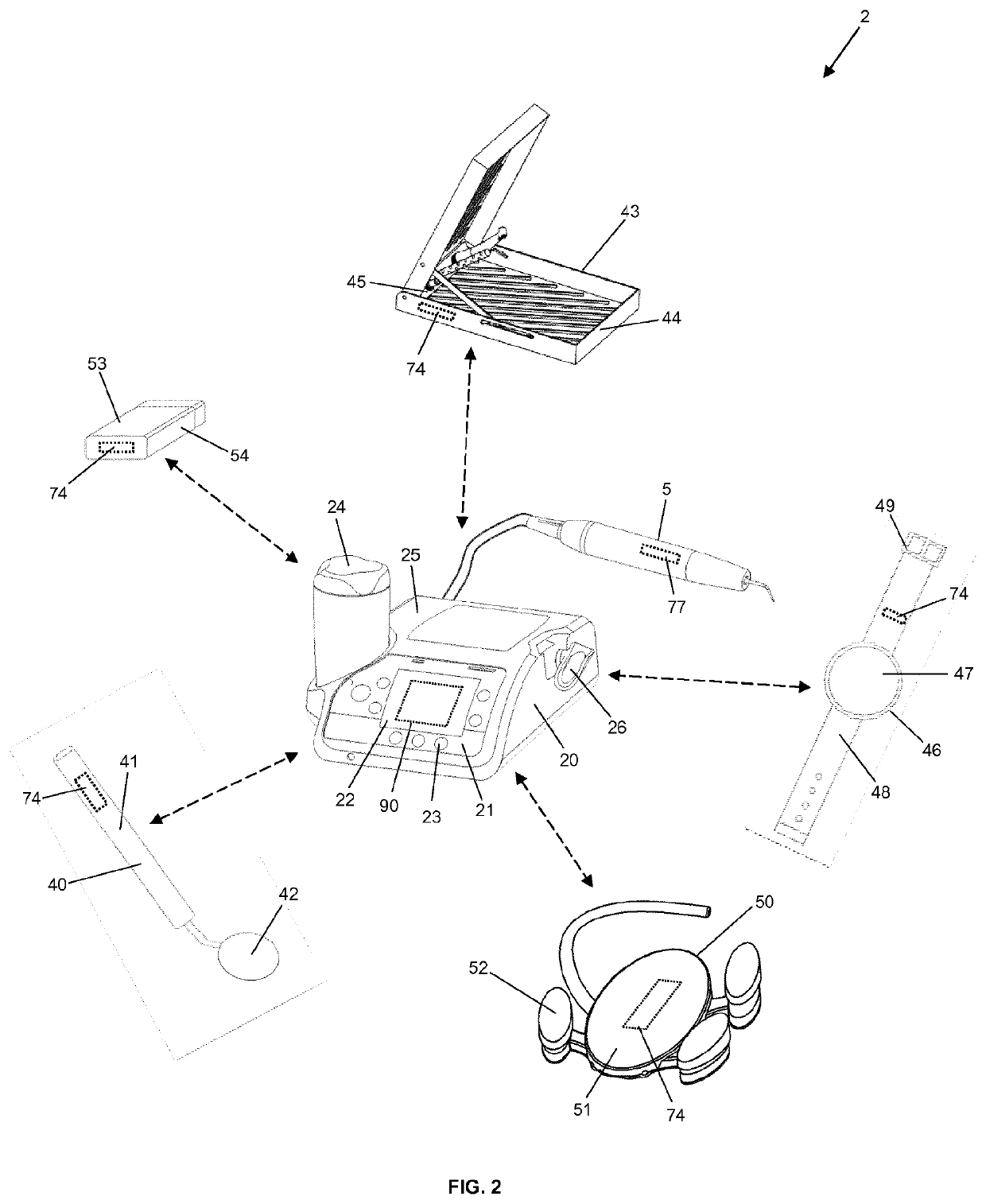
[0045]FIG. 2 shows the medical, in particular the dental system 2 with at least one medical, in particular dental handpiece 5 and a drive unit and / or control unit 20. Furthermore, there are shown several examples of the accessory designed for the operation with the handpiece 5 and / or for the operation with the drive unit and / or control unit 20. For example, the accessory comprises a hand mirror 40, instrument holder 43, display unit 46, foot pedal 50, and identification dement 53 for user identification and comprises a first transmitting and / or receiving unit 74 in each case.

[0046]The drive unit and / or control unit 20 comprises a housing 25 with a handpiece holder 26 and a fluid tank 24. The at least one medical handpiece 5 with the second transmitting and / or receiving unit of FIG. 1 can be coupled to its backside via a supply hose. On the front side, the drive unit and / or control unit 20 comprises a second embodiment of the operating unit 21. In addition to a display 22 and at leas...

fourth embodiment

[0050]the accessory comprises a foot pedal 50 for the drive unit and / or control unit 20. The foot pedal 50 preferably serves to activate an electric drive in the handpiece 5, which is controlled by the control circuit in the drive unit and / or control unit 20. The foot pedal 50 comprises at least one pedal 51 as well at least one operating element 52. The pedal 51 preferably is used to regulate variable parameters, such as different speeds, and the operating element 52 is used to turn on and off the foot pedal 50 and / or to switch between the different variable parameters. When actuated, both elements, the pedal 51 and the operating element 52, send electrical signals to a control unit in the foot pedal 50, which in turn is connected to the first transmitting and / or receiving unit 74. The transmitting and / or receiving unit 74 preferably is located in pedal 51. Alternatively, it can also be positioned in the at least one operating element 52. Electrical signals and / or data, such as rot...


PUM


Abstract

A medical or dental system with at least one first transmitting and / or receiving unit and at least one second transmitting and / or receiving unit, wherein the at least two transmitting and / or receiving units are designed for the capacitive coupling of electric signals into and / or out of a human body, so that an electric path which extends through the human body of the user and / or of the person to be treated can be established for the transmission of electric signals between the at least one first transmitting and / or receiving unit and the at least one second transmitting and / or receiving unit, in order to transmit data between the at least two transmitting and / or receiving units.

Description

CROSS REFERENCE TO RELATED APPLICATION[0001]This application is a U.S. bypass continuation application of International Application No. PCT / EP2015 / 054692, filed Mar. 6, 2015, which in turn claims priority from pending European Patent Application No. EP 14157978.9, filed Mar. 6, 2014, which are incorporated herein by reference.BACKGROUND[0002]Field[0003]The present invention relates to a medical or dental system with at least a first transmitting and / or receiving unit and at least a second transmitting and / or receiving unit, as well as to a method for transmitting electrical signals and / or data between the at least first transmitting and / or receiving unit and the at least second transmitting and / or receiving unit of the medical or dental system.[0004]Description of Prior Art[0005]Such medical or in particular dental systems preferably are used for the processing of human or animal tissues. To this end, they preferably comprise at least one medical, in particular a dental, straight ha...

Claims


Application Information

Patent Timeline
Patent Type & Authority Patents(United States)
IPC IPC(8): A61B34/00A61C3/025A61C1/00A61B90/98A61C17/02H04B13/00A61B18/00A61B17/00A61N5/06
CPCA61C3/025A61B34/25A61C1/0007H04B13/005A61C17/0202A61B18/00A61B90/98A61C1/0015A61B2017/00221A61N2005/0606A61B2562/166A61B2034/258A61B2560/0214A61B2562/164
Inventor SCHRÖCK, RAINERTANNEBAUM, WOLFGANG
Owner W&H DENTALWERK
Why Eureka
Try Eureka