Cathode insulator design

a cathode insulator and cathode technology, applied in the field of cathode insulator design, primary lithium electrochemical cells, can solve the problems of premature discharge of cells, one or both of lithium cluster formation and surface plating

Active Publication Date: 2020-04-21
WILSON GREATBATCH LTD
View PDF13 Cites 0 Cited by
  • Summary
  • Abstract
  • Description
  • Claims
  • Application Information

AI Technical Summary

Benefits of technology

[0011]In illustrative embodiments, the insulator compartment is composed of a material that is substantially impervious to lithium ion flow therethrough and selected from polyethylene, polyethylenechlorotrifluoroethylene, ETFE, polypropylene, and PTFE, and combinations thereof. In some embodiments, an insulator bag partially enveloping the electrode assembly. In illustrative embodiments, the casing is configured as a deep drawn casing structure. In illustrative embodiments, the insulator compartment inhibits fluid flow communication of the electrolyte between the electrode assembly and the at least one anode lead conductively connected to the casing to an extent sufficient to prevent conditions favorable for the formation of lithium clusters between the electrode assembly and the at least one anode lead conductively connected to the casing. In illustrative embodiments, the electrochemical cell is dischargeable without lithium precipitating from the electrolyte in an amount sufficient to permit internal loading of the electrochemical cell.
[0019]In certain embodiments, the casing is configured as a deep drawn casing structure. In some embodiments, the insulator compartment inhibits fluid flow communication of the electrolyte between the cell stack assembly and the at least one anode lead conductively connected to the casing to an extent sufficient to prevent conditions favorable for the formation of lithium clusters between the cell stack assembly and the at least one anode lead conductively connected to the casing.

Problems solved by technology

Reduction of such lithium ions, however, precipitates localized substrate polarization, which can result in one or both of lithium cluster formation and surface plating, i.e., as the concentration gradient relaxes.
And, to the extent that bridging manifests between the negative and positive cell components—via lithium cluster growth—an internal cell loading mechanism is enabled, which can consequently result in the premature discharge of the cell.

Method used


Image

  • Cathode insulator design
  • Cathode insulator design
  • Cathode insulator design

Examples


example 1

gn

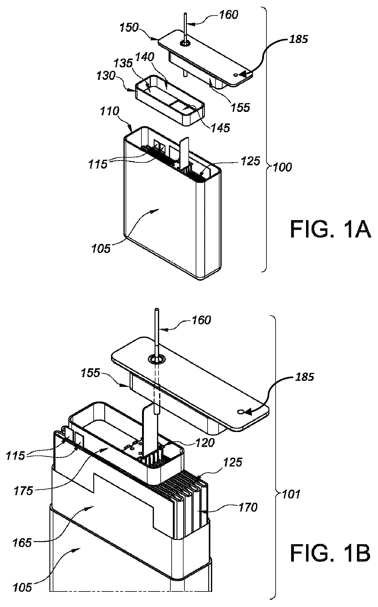
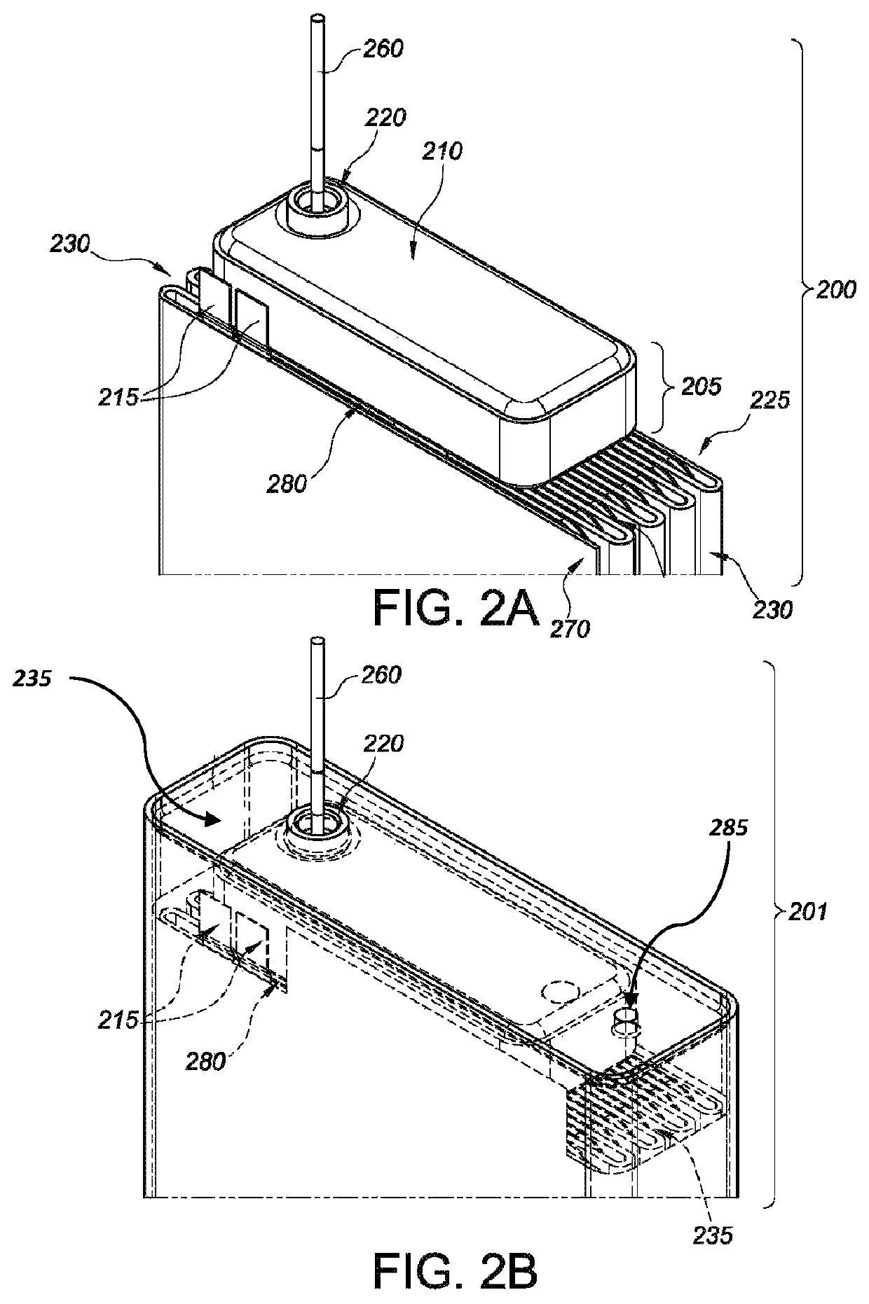
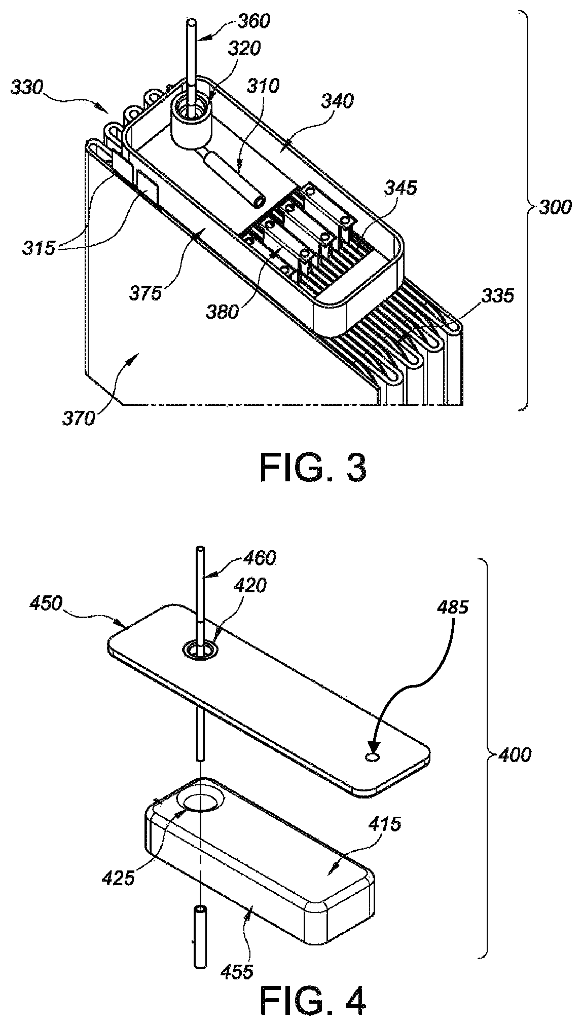
[0107]New insulator designs were tested to evaluate their ability to prevent lithium cluster shorts. Various experimental designs, and control cells, were built, which underwent testing pursuant to harsh “worst case” lithium cluster conditions. The new designs employ overlapping insulator compartments as discussed above, to prevent clusters from entering the insulation pocket, i.e., around the cathode bridge and pin. The new designs also create cluster cavities at either end of the cell, which are un-insulated portions of the case and lid that permit cluster growth in such non-critical areas of the cell.

[0108]Cells were tested per standard discharge parameters, where background is applied prior to the first pulse train, between each pulse train, and then after the final pulse train. The pulse current density was performed within standard protocol ranges. Discharge testing was performed in a “pin down” orientation, which is a 180° rotation in comparison to the electrochemical cells...

example 2

lts

[0109]Cells were discharge tested as outlined in a pin down orientation. The results are detailed below and with respect to Table 1. Typically, “slow” or erratic voltage recovery data indicates that a tested cell shorted during its respective test. Post-test microcal was performed in any event to confirm shorts. All cells showed rising voltage between EOT and start of DA between standard testing ranges except for certain cells that shorted during testing. The results are as follows.

[0110]

TABLE 1Test Identifier (FIG.)Cell DesignResults (No. of Shorts)Design “C”Controls3 / 8Design / Test 2Embodiment 10 / 8Design / Test 3Embodiment 20 / 8

example 3

onal (DA) Results

[0111]Regarding this example, part of the electrochemical cell casing was removed or peeled back to expose side views of the lid area for controls and Embodiments 1-2, as noted above, after the testing was performed. In general, the clusters formed at the lid and in the cluster cavities at both ends of the cell (data not shown). Elevated views of the cell stack and first insulator member for all cells were also studied to ascertain the extent and location of the lithium cluster formation for both the controls and experimental designs, i.e., Embodiments 1-2. With respect to the control cells, cluster formation was observed inside the lid insulator for five cells (data not shown).

[0112]Concerning Embodiments 1 and 2 (Designs 2 and 3), however, essentially no cluster formation was observed in the insulator compartment other than nominal precipitation in two cells, where each had a single isolated cluster therein (data not shown). Design 3 cells did appear to have some ...


PUM

PropertyMeasurementUnit
current densitiesaaaaaaaaaa
sizeaaaaaaaaaa

Abstract

Disclosed herein are electrochemical cells that generally relate to the conversion of chemical energy to electrical energy. More particularly, the present disclosure is directed to primary lithium electrochemical cells possessing insulator pocket structures, which substantially envelope cathode components to prevent lithium cluster formation therein.

Description

CROSS-REFERENCE TO RELATED APPLICATIONS[0001]This application claims priority to U.S. Provisional Patent Application Ser. No. 62 / 417,790 “Insulator Design to Prevent Lithium Clusters,” which was filed on Nov. 4, 2016, the entire contents of which are hereby incorporated by reference in its entirety.FIELD OF THE INVENTION[0002]The present disclosure relates generally to the conversion of chemical energy to electrical energy. In particular, the present disclosure is directed to primary lithium electrochemical cells possessing insulator pocket structures, which substantially envelope cathode components to prevent lithium cluster formation therein.BACKGROUND OF THE INVENTION[0003]The following description is provided to assist the understanding of the reader. None of the information provided or references cited is admitted to be prior art.[0004]High rate intermittent discharge of a lithium-silver vanadium oxide (Li / SVO) electrochemical cell begets voltage and electrolyte gradients withi...

Claims


Application Information

Patent Timeline
Patent Type & Authority Patents(United States)
IPC IPC(8): H01M2/02H01M4/38H01M6/14H01M2/06H01M4/48H01M2/04H01M2/34H01M6/02H01M2/14H01M4/02H01M50/103H01M50/119H01M50/147H01M50/176H01M50/586H01M50/593
CPCH01M2/04H01M4/382H01M6/14H01M2/0277H01M2/34H01M4/38H01M2/06H01M2/14H01M2/0202H01M4/48H01M6/02H01M2200/00H01M2004/027H01M2004/028H01M50/147H01M50/103H01M50/119H01M50/593H01M50/586H01M50/176
Inventor ROY, MARK J.FREITAG, GARYLEHNES, JOSEPH M.DIANETTI, DAVID
Owner WILSON GREATBATCH LTD
Why Eureka
Try Eureka