Fuel-cell unit cell and manufacturing method therefor

a technology of fuel cell unit cells and manufacturing methods, applied in the direction of sustainable manufacturing/processing, final product manufacturing, electrochemical generators, etc., can solve problems such as clogging of gas flow paths

Active Publication Date: 2020-04-28
TOYOTA JIDOSHA KK
View PDF26 Cites 0 Cited by
  • Summary
  • Abstract
  • Description
  • Claims
  • Application Information

AI Technical Summary

Benefits of technology

[0007]According to the fuel-cell unit cell of this aspect, since the melting point of the gas-flow-path forming portion is higher than the melting point of the fusion-bowling portion, fusion and deformation of the gas-flow-path forming portion will be reduced in assembling of the fuel-cell unit cell, making it possible to reduce the possibility that the gas flow paths of the gas-flow-path forming portion may be clogged.
[0009]According to the fuel-cell unit cell of this aspect, since the two first gas-flow-path forming portions and the two second gas-flow-path forming portions are higher in melting point than the first fusion-bonding portion and the second fusion-bonding portion, fusion and deformation of each of the four gas-flow-path forming portions will be reduced in assembling of the fuel-cell unit cell, making it possible to reduce the possibility that the gas flow paths of the gas-flow-path forming portions may be clogged.
[0011]According to the fuel-cell unit cell of this aspect, since the two first gas-flow-path forming portions and the two second gas-flow-path forming portions are formed at mutually non-overlapping positions when projected and observed along a stacking direction in which a plurality of the fuel-cell unit cells are to be stacked together, pressure applied to the separators will be dispersed in assembling of the fuel-cell unit cell, so that deformation of the fuel-cell unit cell will be reduced.
[0013]According to the fuel-cell unit cell of this aspect, since Young's modulus of the inner frame is smaller than Young's modulus of the outer frame, the inner frame is more elastically deformable. Therefore, when the fuel-cell unit cell is used under an environment of larger temperature variations, stresses occurring to the separators and the outer frame will be relaxed by the inner frame, making it possible to reduce the possibility that the electrolyte membrane of the MEGA joined to the inner frame may be broken due to tensile stress.
[0015]According to the fuel-cell unit cell of this aspect, since a seal gasket is formed to pass across a position overlapping with the gas-flow-path forming portion on the cooling surface, part of the pressure applied to the seal gasket will be received by the gas-flow-path forming portion in stacking of a plurality of fuel-cell unit cells, making it possible to reduce deformation of the fuel-cell unit cells.
[0017]According to the method of this aspect, in assembling of the fuel-cell unit cell, since the gas-flow-path forming portion and the thermoplastic bonding portion are compressed and heated at a temperature which is not lower than the melting point of the thermoplastic bonding portion and which is lower than the melting point of the gas-flow-path forming portion, fusion and deformation of the gas-flow-path forming portion will be reduced, making it possible to reduce the possibility that the gas flow paths of the gas-flow-path forming portion may be clogged.

Problems solved by technology

In the related art, when the resin frame and the two separators are joined together by thermal pressing, the gas-flow-path forming portions may be fused and deformed depending on properties of the resin of the gas-flow-path forming portions, and the deformation may cause clogging of the gas flow paths.

Method used


Image

  • Fuel-cell unit cell and manufacturing method therefor
  • Fuel-cell unit cell and manufacturing method therefor
  • Fuel-cell unit cell and manufacturing method therefor

Examples


first embodiment

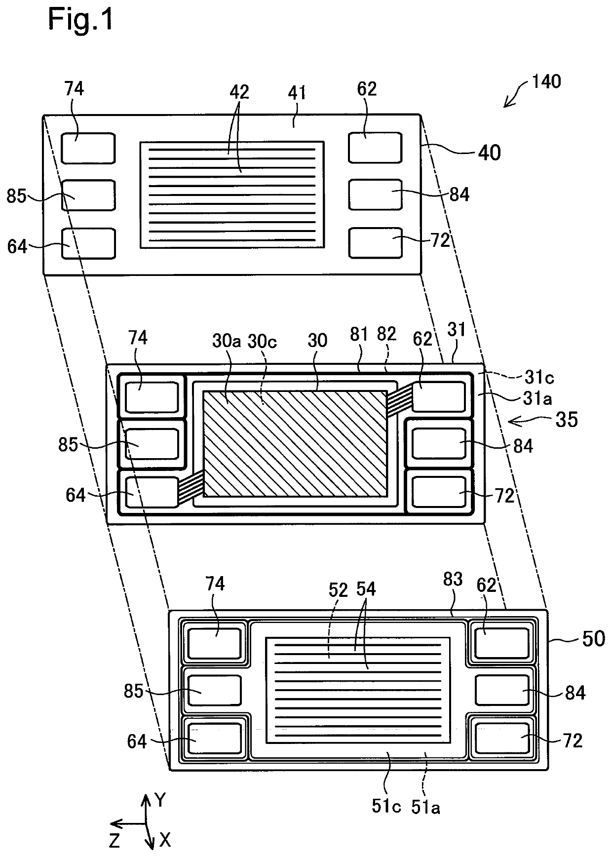
[0027]FIG. 1 is an explanatory view showing a fuel-cell unit cell 140, as it is exploded, according to a first embodiment of the disclosure. The fuel-cell unit cell 140 is, for example, a solid polymer type fuel cell. A fuel cell stack in which this fuel-cell unit cell 140 is stacked in plurality is to be mounted, for example, on a fuel cell vehicle as a power source. Herein, a stacking direction of the fuel-cell unit cells 140 is an X direction, and a horizontal direction is a Z direction. In addition, a direction perpendicular to the stacking direction X and the horizontal direction Z is a vertical direction Y.

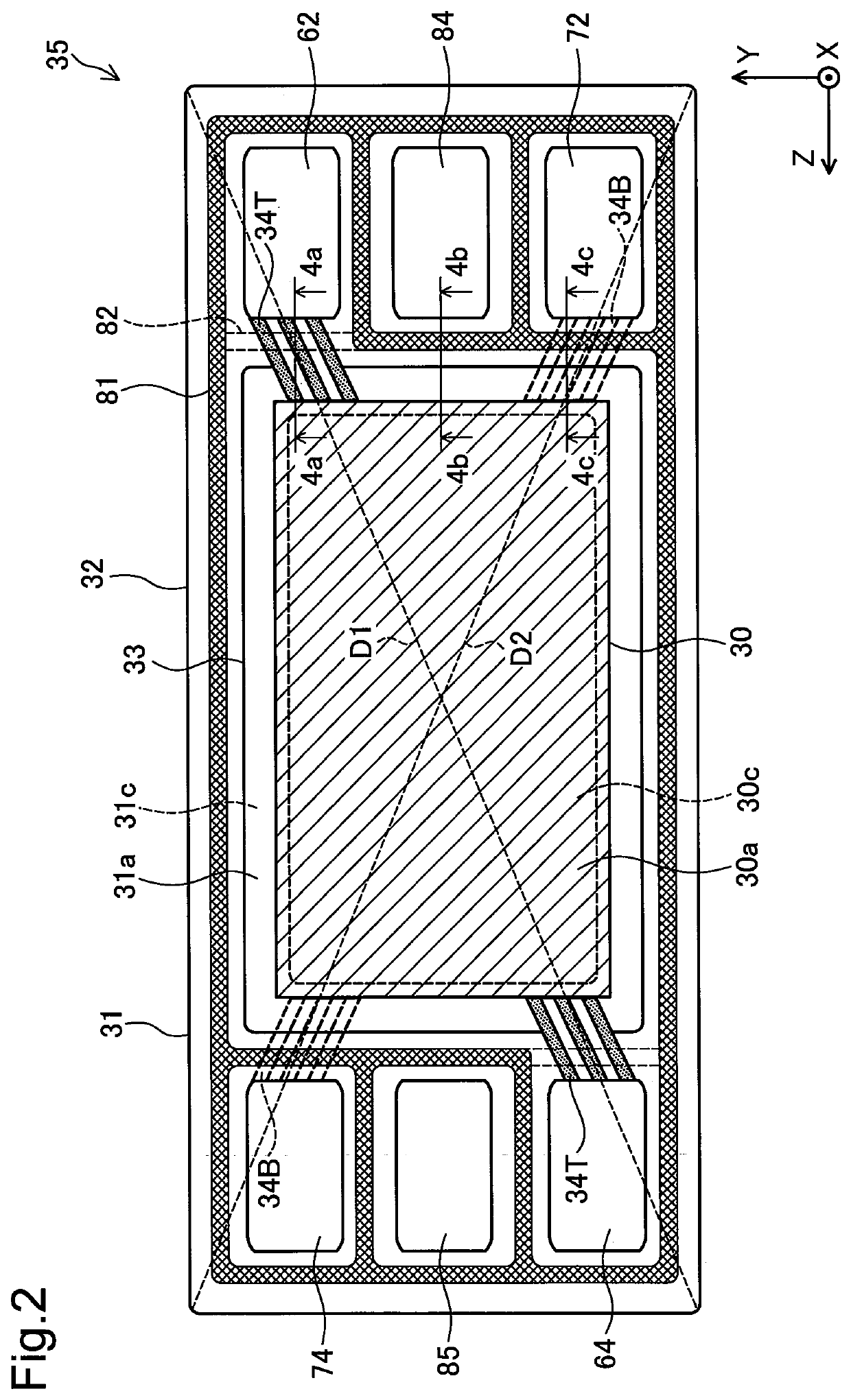
[0028]The fuel-cell unit cell 140 is so configured that a Membrane-Electrode Gas-diffusion-layer Assembly (hereinafter, referred to as ‘MEGA’) plate 35, which includes a MEGA 30 and a resin frame 31 joined to a periphery of the MEGA 30, is sandwiched by a first separator 50 and a second separator 40. In the first embodiment, the first separator 50 is an anode-side separator,...

second embodiment

[0045]FIGS. 6A-6C are explanatory views showing a second embodiment, corresponding to FIGS. 4A-4C of the first embodiment. For drawing convenience' sake, the MEGA 30 is omitted. This embodiment differs from the first embodiment shown in FIGS. 4A-4C only in the materials for forming gas-flow-path forming portions 34Ta, 34Ba, the rest of the constitution being the same as in the first embodiment. As shown in FIG. 6A and FIG. 6C, the gas-flow-path forming portions 34Ta, 34Ba are formed from a material different from that of the inner frame 33 of the resin frame 31 (FIG. 2). The resin frame 31, which includes the gas-flow-path forming portions 34Ta, 34Ba, the inner frame 33, and the outer frame 32 having the thermoplastic bonding portions 81t, 82t integrally molded therewith, may be formed by three-color molding process, for example.

[0046]Also in the second embodiment, resin materials of these members are selected such that the melting point of the gas-flow-path forming portions 34Ta, 3...

third embodiment

[0047]FIGS. 7A-7C are explanatory views showing a third embodiment, corresponding to FIGS. 6A-6C of the second embodiment. This embodiment differs from the second embodiment shown in FIGS. 6A-6C only in the joining method of gas-flow-path forming portions 34Tb, 34Bb with the outer frame 32 of the resin frame 31 (FIG. 2), the rest of the constitution being similar to that of the second embodiment.

[0048]FIGS. 8A-8C illustrate how a first gas-flow-path forming portion 34Tb is joined to the outer frame 32 by using the cross section of FIG. 7A as an example. As shown in FIG. 8A, first, the inner frame 33, and the outer frame 32 with which the second thermoplastic bonding portion 82t is integrally molded, are made by two-color molding process. The first gas-flow-path forming portion 34Tb is modeled separately. Then, the first gas-flow-path forming portion 34Tb is set into contact with the outer frame 32 and joined to the outer frame 32 with heat treatment or adhesive, whereby a cross sect...


PUM

PropertyMeasurementUnit
temperatureaaaaaaaaaa
melting pointaaaaaaaaaa

Abstract

A fuel-cell unit cell comprises an MEGA plate with a resin frame, and two separators. There is formed a gas manifold hole in an outer edge portion of the resin frame. There is provided a gas-flow-path forming portion with a recessed-and-protruded shape on the first surface of the resin frame for forming gas flow paths between the gas manifold hole and the first surface of the MEGA. There is also formed a fusion-bonding portion for surrounding a periphery of the gas manifold hole to cut off gas circulation between the gas manifold hole and the second surface of the MEGA and for bonding the resin frame and the second separator with each other, on the second surface of the resin frame so as to pass across a backside of the gas-flow-path forming portion. The fusion-bonding portion is formed from a first resin, and the gas-flow-path forming portion is formed from a second resin higher in melting point than the first resin.

Description

CROSS REFERENCE TO RELATED APPLICATIONS[0001]This application claims priority to Japanese Patent Application No. 2016-145133 filed on Jul. 25, 2016, the entire contents of which are incorporated by reference herein.BACKGROUNDField[0002]The present disclosure relates to a fuel-cell unit cell and its manufacturing method.Related Art[0003]JP2015-133269A discloses a unit cell for fuel cells. The unit cell includes an electrolyte-membrane / electrode structure, and a resin frame joined to a periphery of the electrolyte-membrane / electrode structure, which is sandwiched between an anode-side separator and a cathode-side separator. Gas manifold holes are formed in outer edge portions of the two separators, respectively, and gas flow paths are formed on respective surfaces of the two separators facing the resin-frame added electrolyte membrane / electrode structure. A plurality of guide flow paths (or gas-flow-path forming portions) that connect the gas manifold holes and the gas flow paths are ...

Claims


Application Information

Patent Timeline
Patent Type & Authority Patents(United States)
IPC IPC(8): H01M8/1004H01M8/0286H01M8/0273H01M8/0258H01M8/0284H01M8/0297H01M8/0267H01M8/248
CPCH01M8/0297H01M8/0284H01M8/0286H01M8/0267H01M8/1004H01M8/0273Y02P70/56H01M8/248H01M8/0258H01M8/0289H01M8/2465Y02P70/50Y02E60/50
Inventor OKADA, SACHIOKURIHARA, TAKUYASHIZUKU, FUMISHIGEMURAYAMA, RYOGOKAMIYA, MAKOTO
Owner TOYOTA JIDOSHA KK
Why Eureka
Try Eureka