Polarizing reflector for multiple beam antennas
a technology of reflectors and antennas, applied in the direction of antennas, antenna earthings, basic electric elements, etc., can solve the problems of reducing the efficiency of antennas
- Summary
- Abstract
- Description
- Claims
- Application Information
AI Technical Summary
Benefits of technology
Problems solved by technology
Method used
Image
Examples
first embodiment
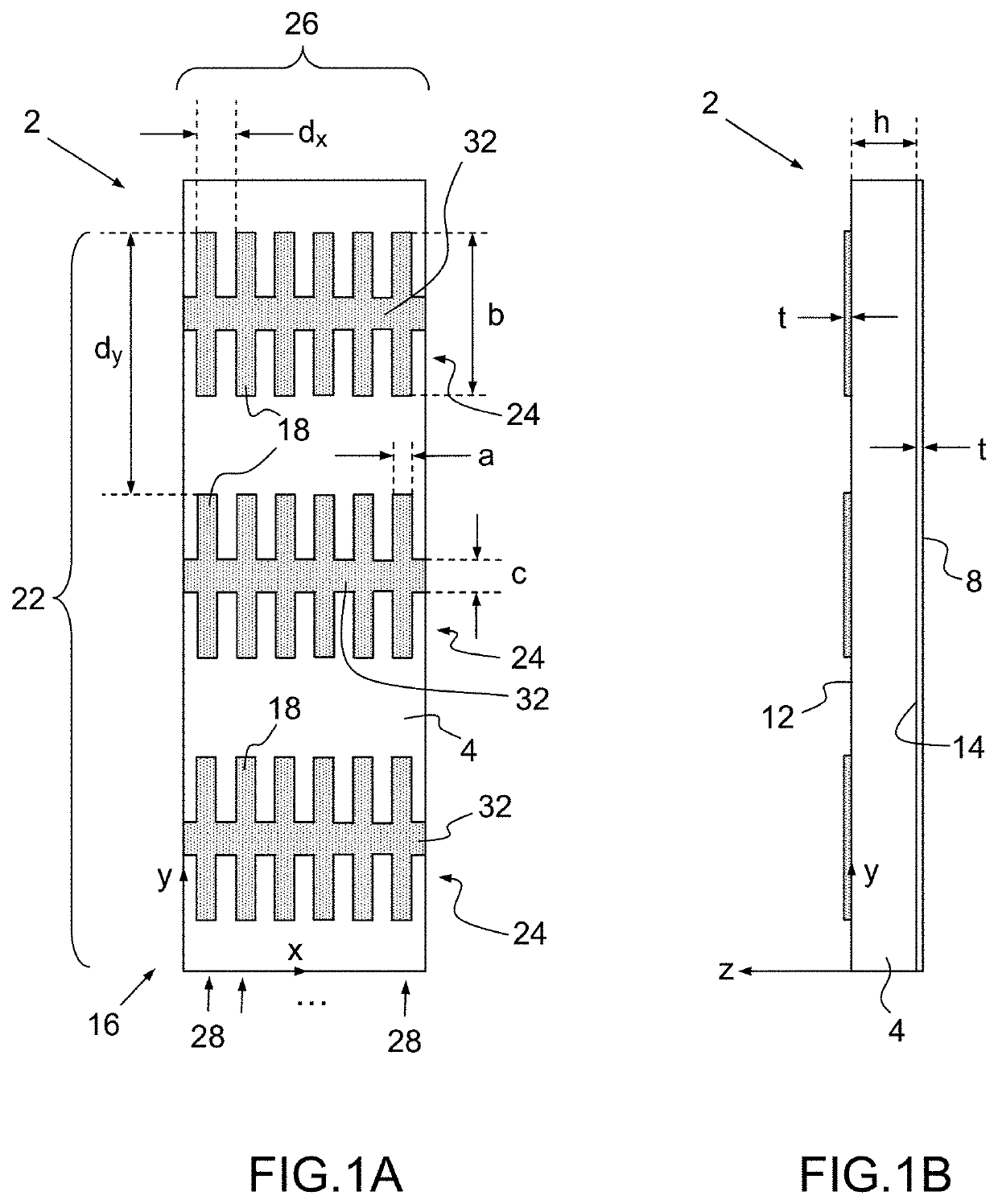
[0089]According to the FIGS. 1A-1B and the invention, a polarizing reflector 2 suited to broadband satellite applications is configured for converting a same linear polarization into a given circular polarization handedness over one frequency band, or into a given circular polarization handedness over a first frequency band and into the orthogonal handedness over a second frequency band.
[0090]The polarizing reflector 2 comprises a flat dielectric substrate 4, a patch array layer 6 and a ground layer 8.
[0091]The flat dielectric substrate 4 is delimited between a first surface 12 and a second surface 14, having a thickness h and a dielectric permittivity εr.
[0092]The patch array layer 6 is formed by a bi-dimensionally periodic lattice 16 of thin metallic patches 18 laid on the first surface 12 of the substrate 4, the periodic lattice 16 having a first set 22 of patch rows 24 oriented along a first direction x with a periodicity dx and a second set 26 of patch columns 28 oriented along...
second embodiment
[0155]According to FIG. 13 and the invention, a polarizing reflector 213 suited to broadband satellite applications is configured for converting a same linear polarization into a given circular polarization handedness over one frequency band, or into a given circular polarization handedness over a first frequency band and into the orthogonal handedness over a second frequency band.
[0156]The polarizing reflector 213 comprises a flat dielectric substrate 214, a patch array layer 216 and a ground layer 218.
[0157]The flat dielectric substrate 214 is delimited between a first surface 222 and a second surface 224, having a thickness h and a dielectric permittivity εr.
[0158]The patch array layer 216 is formed by a first bi-dimensionally periodic lattice 226 of thin metallic patches 228 and a second bi-dimensionally periodic lattice 230 of thin metallic patches 228, both laid on the first surface 222 of the substrate 214.
[0159]The first and second periodic lattices 226, 230 having each a fi...
third embodiment
[0181]According to the FIG. 16 and the polarizing reflector, a flat polarizing reflector 352 for a broadband antenna is locally illuminated at normal or oblique incidence by an electromagnetic source 354 (or feeder) having a predetermined radiation pattern to the flat polarizing reflector.
[0182]The flat polarizing reflector 352 is configured for converting locally a linear polarization Einc into a given local circular polarization handedness over one frequency band when operating in a single wideband at a local normal or oblique incidence illuminated by a local plane wave originated from a predetermined radiation source pattern, or into a first local circular polarization handedness over a first frequency band and into a second local polarization handedness over a second frequency, the first and the second local circular polarization handedness being substantially equal or orthogonal when operating in dual-band at normal or oblique incidence illuminated by a local plane wave origina...
PUM
 Abstract
Description
Claims
Application Information
 - R&D
- Intellectual Property
- Life Sciences
- Materials
- Tech Scout
- Unparalleled Data Quality
- Higher Quality Content
- 60% Fewer Hallucinations
Browse by: Latest US Patents, China's latest patents, Technical Efficacy Thesaurus, Application Domain, Technology Topic, Popular Technical Reports.
© 2025 PatSnap. All rights reserved.Legal|Privacy policy|Modern Slavery Act Transparency Statement|Sitemap|About US| Contact US: help@patsnap.com


