Mowing or grinding device

a technology mowing blade, which is applied in the direction of mowing machines, grain treatment, agriculture tools and machines, etc., can solve the problems of affecting the service life of mowing or grinding device, and achieve the effect of ensuring the stability of the operating position of the tool and satisfying the resistance to wear and tear

Active Publication Date: 2020-05-05
ACTIBAC
View PDF16 Cites 1 Cited by
  • Summary
  • Abstract
  • Description
  • Claims
  • Application Information

AI Technical Summary

Benefits of technology

[0008]A concept underlying the invention is to propose a mowing or grinding device of the aforesaid type which allows th

Problems solved by technology

It has nevertheless been noted that such axial supports and mounting apertures have been subject to wear and to ra

Method used


Image

  • Mowing or grinding device
  • Mowing or grinding device
  • Mowing or grinding device

Examples


first embodiment

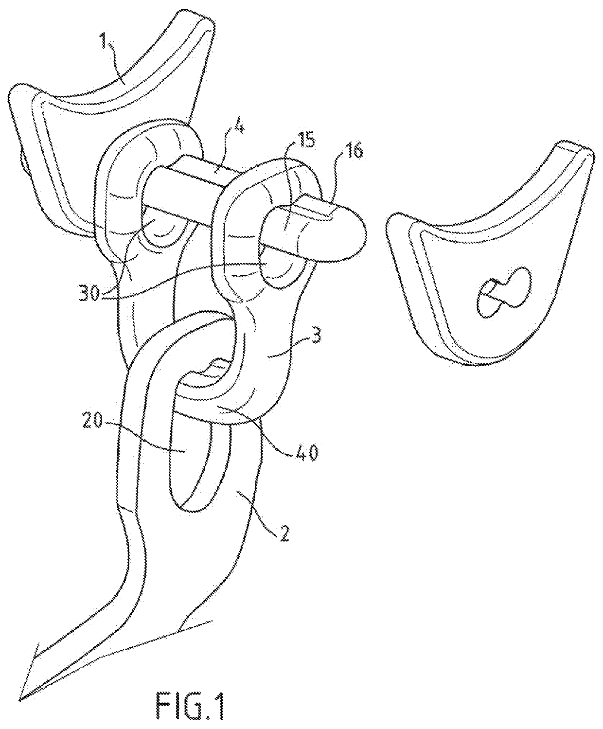
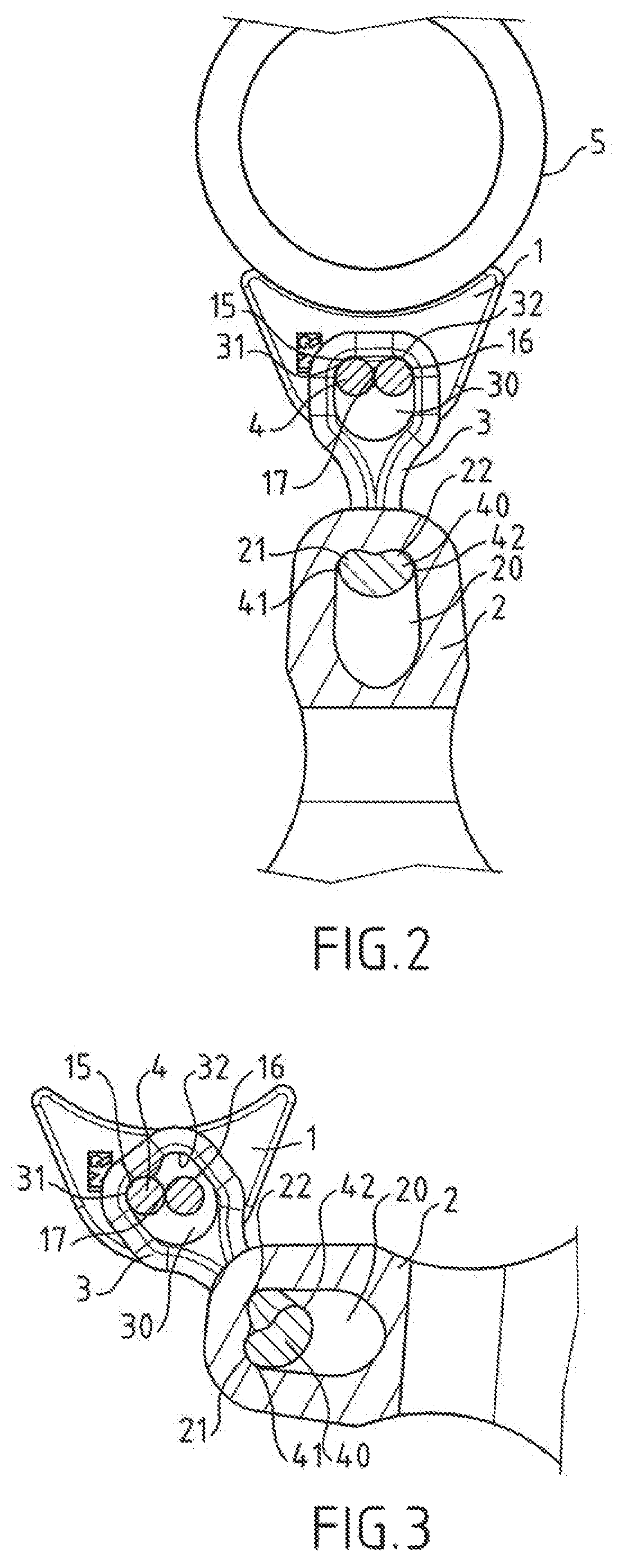
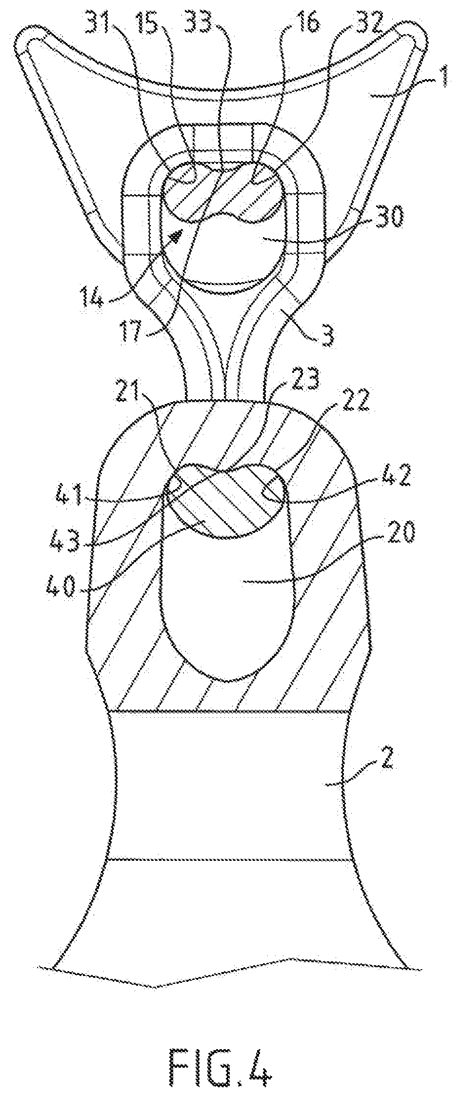
[0043]FIGS. 1 to 3 show a mowing or grinding device according to a

[0044]The device comprises a plurality of mowing or grinding tools 2, just one of which is shown here, which are connected to a rotatable shaft 5, which is generally hollow, shown in FIG. 2. The rotatable shaft 5 can be rotatably mounted on a cutting or grinding machine, along a horizontal, vertical or oblique rotational axis.

[0045]The tool 2 is connected to the rotatable shaft 5 either directly or by means of a shackle 3, as shown in the embodiment illustrated. The tool 2 is mounted in a hinged manner with respect to the rotatable shaft 5 so as to be able to be positioned, under the effect of the centrifugal force engendered by the rotation of the rotatable shaft, in an operating position in which it is arranged radially with respect to the rotatable shaft 5 and to be retracted by moving away from its operating position when it meets an obstacle. The tool 2 comprises a cutter which constitutes an operating part which...

third embodiment

[0060]FIGS. 6 and 7 show the devices respectively in a second and In said embodiments, only the connection between the tool 2 and the shackle 3 or the connection between the shackle 3 and the rotatable shaft 5 is obtained by means of a hinged connection with preferred positioning such as described above.

[0061]Thus, in FIG. 6, the axial support which is carried by the flanges 1 which are fixed to the rotatable shaft 5 is a simple cylindrical rod 50 and the mounting apertures of the shackle 3 are simple circular apertures 51 through which the cylindrical rod 50 passes.

[0062]In FIG. 7 it is the connection between the shackle 3 and the tool 2 which is simplified. Thus, the axial support of the shackle 3 is a cylindrical rod 52 and the mounting aperture 20 of the tool 2 is an opening with an oblong shape 53, into the interior of which the cylindrical rod 52 passes.

[0063]In all the embodiments described above, for each hinged connection with preferred positioning, the two concave housing...


PUM


Abstract

A mowing or grinding device comprising a rotatable shaft which carries a plurality of mowing or grinding tools which form flails, each tool being mounted directly or indirectly on the rotatable shaft by means of at least one hinged connection with preferred positioning, which allows keeping the tool in the operating position to be favored and comprises a mounting aperture and an axial support which passes through the mounting aperture; the device being characterized in that the positioning portion of the axial support has at least one cylindrical boss which has a circular surface and the positioning portion of the mounting aperture has at least one concave housing which has a circular surface which is capable of receiving the circular surface of the cylindrical boss when the tool is in the operating position, the circular surface of the concave housing having a constant curve which is complementary to the circular surface of the cylindrical boss over a periphery which is greater than a quarter circle.

Description

CROSS-REFERENCE TO RELATED APPLICATIONS AND CLAIM TO PRIORITY[0001]This application is a national stage application of International Application No. PCT / FR2015 / 053353 filed Dec. 7, 2015, which claims priority to French Patent Application No. 1462479 filed Dec. 16, 2014, the disclosures of which are incorporated herein by reference and to which priority is claimed.FIELD OF THE INVENTION[0002]The invention relates to the area of mowing or grinding devices.[0003]Such mowing or grinding devices are fitted notably on machines for cutting and / or grinding vegetal products such as rotary mowers which are used for cutting crops and flail mowers which are used for maintaining green spaces or roadside verges.BACKGROUND OF THE INVENTION[0004]The mowing or grinding devices comprise a rotatable shaft which carries tools which operate in the manner of flails during the rotation of the shaft. The rotatable shaft is provided with flanges which are positioned perpendicularly with respect to its axis,...

Claims


Application Information

Patent Timeline
IPC IPC(8): A01D34/535B02C18/18
CPCB02C18/18A01D34/535
Inventor BACHMANN, CHRISTOPHE
Owner ACTIBAC
Why Eureka
Try Eureka