
Hybrid combustor assembly and method of operation

a combustor and hybrid technology, applied in the direction of machines/engines, composite engine plants, lighting and heating apparatus, etc., can solve the problems of reducing the efficiency benefits of the inefficient rotating detonation combustion system at more than one operating condition

Active Publication Date: 2020-05-05
GENERAL ELECTRIC CO
View PDF19 Cites 1 Cited by
  • Summary
  • Abstract
  • Description
  • Claims
  • Application Information

AI Technical Summary

Benefits of technology

The hybrid system improves specific fuel consumption and fuel burn efficiency while maintaining operability at various conditions, allowing the RDC system to operate effectively at steady-state pressures and temperatures, while the primary combustion chamber handles transient conditions.

Problems solved by technology

However, such may reduce the efficiency benefits of the rotating detonation combustion system.
Various combinations of fuel-oxidizer mixture, pressure, temperature, and stoichiometric ratio (e.g., at various operating conditions of the propulsion system) generally renders a rotating detonation combustion system inefficient at more than one operating condition.

Method used


Image

  • Hybrid combustor assembly and method of operation
  • Hybrid combustor assembly and method of operation
  • Hybrid combustor assembly and method of operation

Examples


Embodiment Construction

[0028]Reference will now be made in detail to present embodiments of the invention, one or more examples of which are illustrated in the accompanying drawings. The detailed description uses numerical and letter designations to refer to features in the drawings. Like or similar designations in the drawings and description have been used to refer to like or similar parts of the invention.

[0029]As used herein, the terms “first”, “second”, and “third” may be used interchangeably to distinguish one component from another and are not intended to signify location or importance of the individual components.

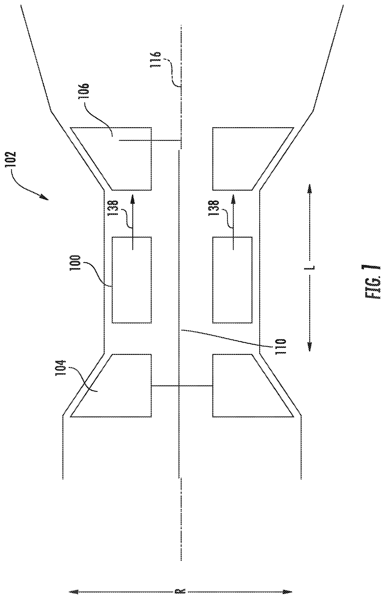
[0030]The terms “forward” and “aft” refer to relative positions within a propulsion system or vehicle, and refer to the normal operational attitude of the propulsion system or vehicle. For example, with regard to a propulsion system, forward refers to a position closer to a propulsion system inlet and aft refers to a position closer to a propulsion system nozzle or exhaust.

[0031]The terms...


PUM


Abstract

A hybrid combustion system, and method of operation, for a propulsion system is provided. The hybrid combustion system defines a radial direction, a circumferential direction, and a longitudinal centerline in common with the propulsion system extended along a longitudinal direction. The hybrid combustion system includes a rotating detonation combustion (RDC) system comprising an annular outer wall and an annular inner wall each generally concentric to the longitudinal centerline and together defining a RDC chamber and a RDC inlet, the RDC system further comprising a nozzle located at the RDC inlet defined by a nozzle wall. The nozzle defines a lengthwise direction extended between a nozzle inlet and a nozzle outlet along the lengthwise direction, and the nozzle inlet is configured to receive a flow of oxidizer. The nozzle further defines a throat between the nozzle inlet and the nozzle outlet, and wherein the nozzle defines a converging-diverging nozzle. The hybrid combustion system further includes an inner liner extended generally along the longitudinal direction; an outer liner extended generally along the longitudinal direction and disposed outward of the inner liner along the radial direction; a bulkhead wall disposed at the upstream end of the inner and outer liners, in which the bulkhead wall extends generally in the radial direction and couples the inner liner and the outer liner, and wherein the inner liner, the outer liner, and the bulkhead wall together define a primary combustion chamber, and further wherein the RDC system and bulkhead wall together define a RDC outlet through the bulkhead wall and adjacent to the primary combustion chamber; and a fuel manifold assembly extended at least partially through the bulkhead wall, in which the fuel manifold assembly defines a fuel manifold assembly exit disposed adjacent to the primary combustion chamber.

Description

FIELD[0001]The present subject matter relates generally to a system of continuous detonation in a propulsion system.BACKGROUND[0002]Many propulsion systems, such as gas turbine engines, are based on the Brayton Cycle, where air is compressed adiabatically, heat is added at constant pressure, the resulting hot gas is expanded in a turbine, and heat is rejected at constant pressure. The energy above that required to drive the compression system is then available for propulsion or other work. Such propulsion systems generally rely upon deflagrative combustion to burn a fuel / air mixture and produce combustion gas products which travel at relatively slow rates and constant pressure within a combustion chamber. While engines based on the Brayton Cycle have reached a high level of thermodynamic efficiency by steady improvements in component efficiencies and increases in pressure ratio and peak temperature, further improvements are welcomed nonetheless.[0003]Accordingly, improvements in eng...

Claims


Application Information

Patent Timeline
Patent Type & Authority Patents(United States)
IPC IPC(8): F02C3/16F02K7/10F02K7/20F02K7/08F02K7/00F23R7/00F23R3/58F02C7/22F23R3/00
CPCF02K7/08F02K7/10F23R7/00F02C7/222F23R3/58F23R3/002F02C3/16F02K7/00F02K7/20F23R2900/00015F23R3/38F23R3/52
Inventor VISE, STEVEN CLAYTONZELINA, JOSEPHJOHNSON, ARTHUR WESLEYCOOPER, CLAYTON STUARTPAL, SIBTOSH
Owner GENERAL ELECTRIC CO
Learn More