Spanning connector for implantable hearing instrument

a technology of spanning connector and hearing instrument, which is applied in the field of spanning connector for implantable hearing instruments, can solve the problems of affecting the number of people with moderate or greater hearing loss, the inability of sound to pass effectively through the middle ear to the cochlea and auditory nerve, and the inability to align the vibratory actuator of the middle ear transducer with the auditory transducer

Active Publication Date: 2020-05-05
COCHLEAR LIMITED
View PDF18 Cites 0 Cited by
  • Summary
  • Abstract
  • Description
  • Claims
  • Application Information

AI Technical Summary

Benefits of technology

[0008]That is, a number of people who exhibit a moderate or greater degree of hearing loss are affected by complications to the conductive components of the middle ear. Sound cannot pass effectively through the middle ear to the cochlea and auditory nerve. Such complications may arise due to disease such as otosclerosis where abnormal growth of bone affects the function of the ossicles, or aural atresia where no external ear canal or tympanic membrane exists. Further, the interconnection between the ossicle bones may be degraded to a point that these bones no longer effectively transmit vibratory signals. In these and other instances, it has been determined that direct interconnection to the stapes, oval window and / or round window may allow for bypassing malformed, missing and / or degraded ossicle bones and thereby provide for improved transmission of vibratory signals.
[0009]To interconnect a middle ear transducer to the stapes, the stapes footplate, oval window and / or round window, an implantable hearing instrument will typically access the attic region of the tympanic cavity through the mastoid process. However, access to the attic region of the tympanic cavity may not provide direct access to the stapes / windows region. In this regard, the axis of movement of an actuator of an implantable hearing instrument may not align linearly with the auditory component of interest. Of note, the stapes works similarly to a piston to displace fluid within the cochlea via its interface with the oval window. Movement of the stapes in a direction that is substantially normal to the interface between the stapes and oval window is a near natural movement in a health ear and typically provides the most effective / efficient auditory stimulation. Accordingly, the non-linear alignment of a movement axis of a vibratory actuator device relative to that interface may result in reduced vibratory transfer and, hence, reduced auditory stimulation.
[0012]The second end of the connector that contacts the auditory component may engage the auditory component in any appropriate manner. In one arrangement, this end of the connector may be disposed against (e.g., biased against) a surface of, for example, an ossicle bone, the oval window or the round window. In other arrangements, this contact end may clip to or straddle a portion of an auditory component (e.g., ossicles). In one specific arrangement, the contact end may engage the stapes head using, for example, a recessed (e.g., cup or bell shaped) coupler. Alternatively, the connector may interconnect to the stapes footplate using, for example, a straight wire that may be inserted into a shallow hole formed within the footplate. In another arrangement, a detachable connector may be utilized. In this arrangement, a first portion of the connector may be permanently affixed to the auditory component. A second portion of the connector may releasably engage the first portion. Accordingly, this may permit selective removal of the hearing instrument without further disturbing the patient's auditory system.
[0013]The first end of the connector may be attached to a stationary structure of the middle ear (e.g., tympanic cavity wall) in any appropriate manner. In one arrangement, the first end of the connector includes one or more apertures that may be utilized to fixedly connect the first end to a bone structure. For instance, such apertures may receive one or more bone screws. Likewise, one or more apertures may allow for oseointegration of the first end of the connector with underlying bone structure.
[0017]In one arrangement, the elastic member is an elongated member. This elongated member may further be plastically deformable in response to an applied stress in order to shape the member for placement within a patient's tympanic cavity. Once deformed to a desired shape, the elastic member may retain elasticity that allows elastic deformation in response to displacement by the actuator.

Problems solved by technology

In such instances, aligning the vibratory actuator of the middle ear transducer with the auditory transducer remains problematic.
That is, a number of people who exhibit a moderate or greater degree of hearing loss are affected by complications to the conductive components of the middle ear.
Sound cannot pass effectively through the middle ear to the cochlea and auditory nerve.
Such complications may arise due to disease such as otosclerosis where abnormal growth of bone affects the function of the ossicles, or aural atresia where no external ear canal or tympanic membrane exists.
Further, the interconnection between the ossicle bones may be degraded to a point that these bones no longer effectively transmit vibratory signals.
However, access to the attic region of the tympanic cavity may not provide direct access to the stapes / windows region.
Accordingly, the non-linear alignment of a movement axis of a vibratory actuator device relative to that interface may result in reduced vibratory transfer and, hence, reduced auditory stimulation.

Method used


Image

  • Spanning connector for implantable hearing instrument
  • Spanning connector for implantable hearing instrument
  • Spanning connector for implantable hearing instrument

Examples


Embodiment Construction

[0025]Reference will now be made to the accompanying drawings, which at least assist in illustrating the various pertinent features of the present invention. The following description is presented for purposes of illustration and description and is not intended to limit the invention to the form disclosed herein. Consequently, variations and modifications commensurate with the following teachings, and skill and knowledge of the relevant art, are within the scope of the present invention. The embodiments described herein are further intended to explain the best modes known of practicing the invention and to enable others skilled in the art to utilize the invention in such, or other embodiments and with various modifications required by the particular application(s) or use(s) of the present invention.

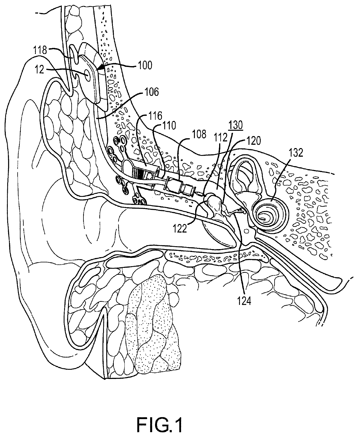
[0026]FIG. 1 illustrates one application of the present invention. As illustrated, the application illustrates a fully implantable hearing instrument. However, it will be appreciated that...


PUM


Abstract

Provided herein are various connectors that allow for translating the axial movement of an implantable hearing transducer from a first direction to a second direction. In various arrangements, these connectors form a spanning connector that extend across a portion of a tympanic cavity of a patient. One end of the connector can be affixed to the tympanic cavity, and a second end may engage an auditory component. In such an arrangement, a vibratory actuator may engage the connector between the first and second ends. Such an arrangement can provide improved alignment of actuator movement with a direction of movement of an auditory component.

Description

CROSS REFERENCE TO RELATED APPLICATION[0001]This application claims the benefit of the filing date of U.S. Provisional Application No. 60 / 986,523 entitled “Spanning Connector for Implantable Hearing Instrument” having a filing date of Nov. 8, 2007, the entire contents of which are incorporated herein by reference.FIELD OF THE INVENTION[0002]The present invention relates to an apparatus and method (i.e., utility) for interfacing an implantable hearing instrument with a patient's auditory system. More particularly, the utility permits efficient coupling of mechanical transducer to an auditory component when the mechanical transducer and auditory component are misaligned.BACKGROUND OF THE INVENTION[0003]In the class of hearing aid systems generally referred to as implantable hearing instruments, some or all of various hearing augmentation componentry is positioned subcutaneously on or within a patient's skull, typically at locations proximate the mastoid process. In this regard, implan...

Claims


Application Information

Patent Timeline
Patent Type & Authority Patents(United States)
IPC IPC(8): H04R25/00A61F2/18
CPCH04R25/606A61F2002/183
Inventor PERGOLA, NICHOLAS
Owner COCHLEAR LIMITED
Why Eureka
Try Eureka