Supercharge Your Innovation With Domain-Expert AI Agents!

Means for controlling a pitch change system comprising an anti-rotation device, a pitch change system equipped with said control means, and a corresponding turbine engine

a technology of a control means and a control means, which is applied in the field of aeronautical propulsion, can solve the problems of not allowing a homogeneous supply of load-transfer bearings, affecting the homogeneity of lubrication, and complicating the assembly of the pitch change system, so as to save time, maintain the structural integrity of the crossmember, and not congest the environment

Active Publication Date: 2020-05-12
SN DETUDE & DE CONSTR DE MOTEURS DAVIATION S N E C M A
View PDF27 Cites 0 Cited by
  • Summary
  • Abstract
  • Description
  • Claims
  • Application Information

AI Technical Summary

Benefits of technology

The invention allows for the placement of a crossmember outside the movable and fixed parts of a control system, which prevents the movable part from rotating and allows for the installation of additional equipment without affecting the weight or environment of the turbine engine. The crossmember also allows for the installation of instrumentation without obstructing the anti-rotation function, and avoids the use of bridging, clamps, and cable assemblies. Overall, the invention improves the efficiency and reliability of control systems for turbine engines.

Problems solved by technology

However, an anti-rotation bar 22 of this type is installed between the movable member 29 and the fixed member 28 of the control means 27, and passes through chambers of the movable member 29, which complicates the assembly of the pitch change system.
Secondly, this configuration does not allow a homogeneous supply of the load-transfer bearing 19 which is located radially above the movable member 29.
This results in a problem in terms of the homogeneity of the lubrication of the load-transfer bearing 19.

Method used


Image

  • Means for controlling a pitch change system comprising an anti-rotation device, a pitch change system equipped with said control means, and a corresponding turbine engine
  • Means for controlling a pitch change system comprising an anti-rotation device, a pitch change system equipped with said control means, and a corresponding turbine engine
  • Means for controlling a pitch change system comprising an anti-rotation device, a pitch change system equipped with said control means, and a corresponding turbine engine

Examples


Embodiment Construction

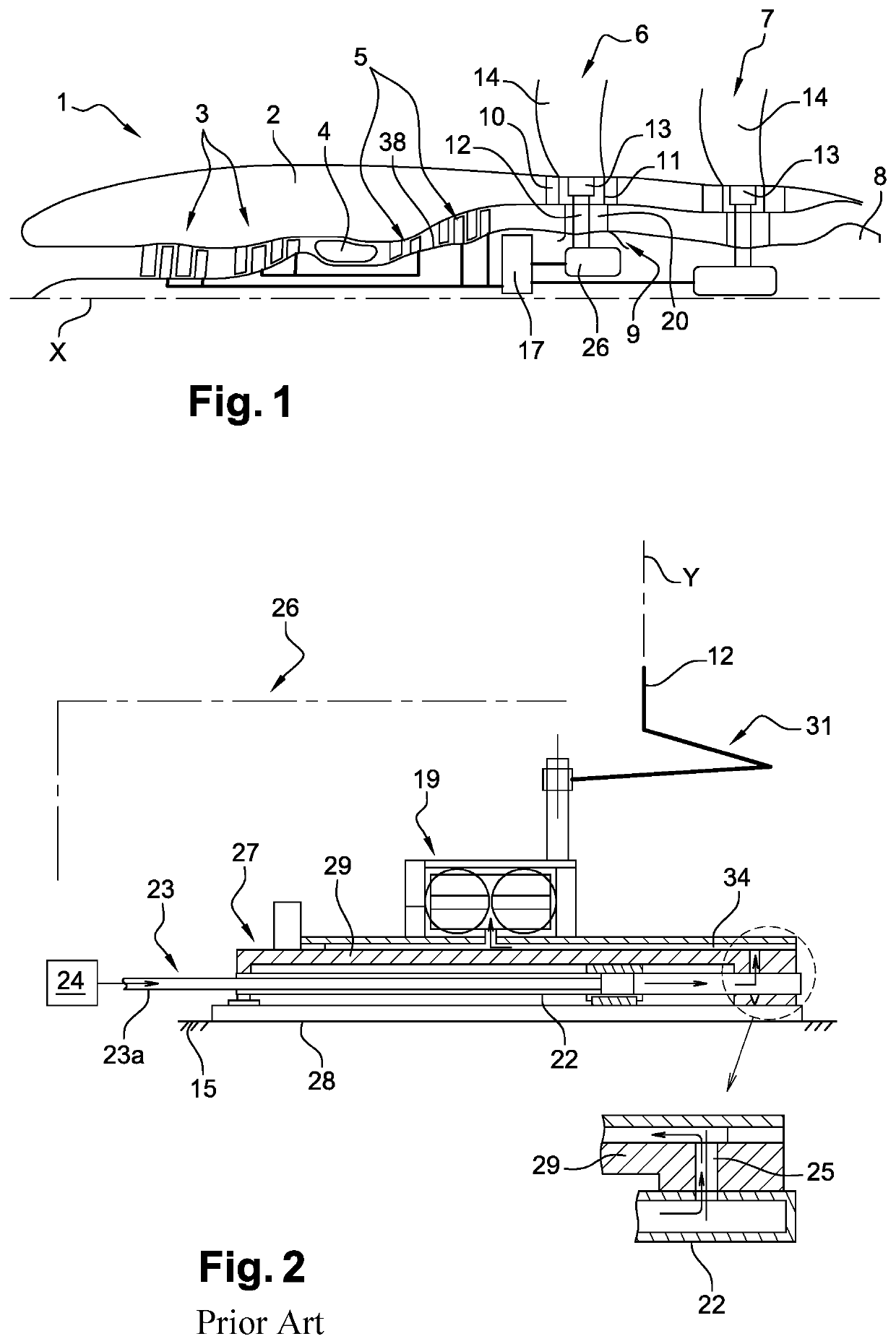
[0034]FIG. 1 and the rest of the description show and describe a turboprop engine having a longitudinal axis X and an unducted fan, which engine is intended to be mounted on an aircraft. However, the invention can be applied to other types of turbine engine. The corresponding reference numerals of the elements of the turboprop engine described previously will be used throughout the rest of the description.

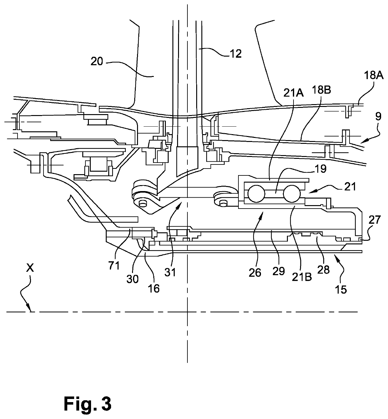
[0035]According to FIG. 3, the turbine engine comprises a pitch change system 26 for changing the pitch of the blades 14 of the propeller 6, making it possible to vary the calibration or the pitch of the blades 14 around the radial axes Y thereof in such a way that said blades occupy angular positions according to the operating conditions of the turbine engine and the flight phases in question. The radial axis Y in this case is perpendicular to the longitudinal axis X. The system 26 comprises a control means 27 controlling the pitch change of each of the blades 14 and a linking mec...


PUM


Abstract

A controller for controlling a system for changing the pitch of blades of a turbine engine propeller, the controller includes a fixed member (28) and a member (29) which is movable in translation along a longitudinal axis (X) relative to the fixed member (28), and an anti-rotation device (33) configured so as to prevent the rotation of the movable member (29) relative to the fixed member (28) about the axis (X). The anti-rotation device includes a longitudinal structural crossmember (35) which is mounted by a first and a second end (36, 37) on the fixed member, and support and guide unit (57) integrally in translation the movable member along the axis (X), the crossmember extending radially outside the movable member and the fixed member relative to a radial axis (Y) which is perpendicular to the axis (X) and being guided through the support and guide unit.

Description

1. FIELD OF THE INVENTION[0001]The present invention relates to the field of aeronautic propulsion. It relates to a means for controlling a system for changing the pitch of a blade of a propeller comprising an anti-rotation device, said device making it possible to prevent the rotation of a movable member relative to a fixed member of said control means. It also relates to a pitch change system equipped with a control means and to the corresponding turbine engine.2. PRIOR ART[0002]Changing the pitch or variable calibration of the blades of a turbine engine propeller is one of the ways to improve the performance and efficiency of turbine engines in different flight conditions.[0003]Turbine engines such as turboprop engines having two propulsion propellers, for example contra-rotating propellers, which are also referred to as “open rotor” and “unducted fan”, are known which are equipped with these pitch change systems. Turboprop engines can be distinguished from turbojet engines in th...

Claims


Application Information

Patent Timeline
Patent Type & Authority Patents(United States)
IPC IPC(8): F02C7/06F01D25/18B64C11/32
CPCB64C11/32F01D25/18F02C7/06F05D2260/98F05D2220/323F05D2240/54B64C11/303Y02T50/60
Inventor TAJAN, SÉBASTIEN EMILE PHILIPPESOURYAVONGSA, EDDY KEOMORAKOTTSERVANT, REGIS EUGÉNE HENRIFABRE, ADRIEN JACQUES PHILIPPEIBARZO, STEPHANE
Owner SN DETUDE & DE CONSTR DE MOTEURS DAVIATION S N E C M A
Features
  • R&D
  • Intellectual Property
  • Life Sciences
  • Materials
  • Tech Scout
  • Unparalleled Data Quality
  • Higher Quality Content
  • 60% Fewer Hallucinations
Learn More