Method for manufacturing panel element

a technology of panel elements and manufacturing methods, applied in the direction of instruments, illuminated signs, display means, etc., can solve the problems of double projection of illumination portions and light leakag

Active Publication Date: 2020-05-19
SANWA SCREEN
View PDF10 Cites 2 Cited by
  • Summary
  • Abstract
  • Description
  • Claims
  • Application Information

AI Technical Summary

Benefits of technology

[0008]The present invention has been achieved in view of these circumstances, and an object of the present invention is to provide a method for manufacturing a panel element capable of preventing light leakage to obtain a clear character or graphic.
[0017]In this structure, after performing the process of printing the third printed layer on the back side of the transparent sheet, a hole portion is formed at a position corresponding to the third printed layer in the process of forming the hole portion in the laminated printed layer. This makes it possible to visually recognize the third printed layer through the hole portion in the shape of the target character or graphic. Decorativeness of the panel element can be improved by being manufactured with this manufacturing method.
[0020]In addition, in the method for manufacturing the panel element according to an aspect of the present invention, the third printed layer preferably includes a colored layer colored in a predetermined color and a white layer that prevents light to be emitted to the front side of the panel element directly by letting light passing through only the transparent sheet.
[0021]In this structure, by printing the colored layer, it is possible to apply a decoration in which a predetermined color can be visually recognized through the hole portion of the panel element. In addition, by printing the white layer, it is possible to prevent light from being directly emitted to the front side of the panel element.

Problems solved by technology

However, in such a structure, due to light passing through an upper printed layer, light leakage occurs in a peripheral portion of the illumination portion (character or graphic) to blur the illumination portion.
Meanwhile, if the light shielding printed layer is provided on a surface of the back surface protective layer, a problem that the illumination portion is doubly projected because the shadow of light from the light shielding printed layer on the back side is picked up occur.

Method used


Image

  • Method for manufacturing panel element
  • Method for manufacturing panel element
  • Method for manufacturing panel element

Examples


Embodiment Construction

[0028]Hereinafter, an embodiment of a panel element according to an aspect of the present invention is described.

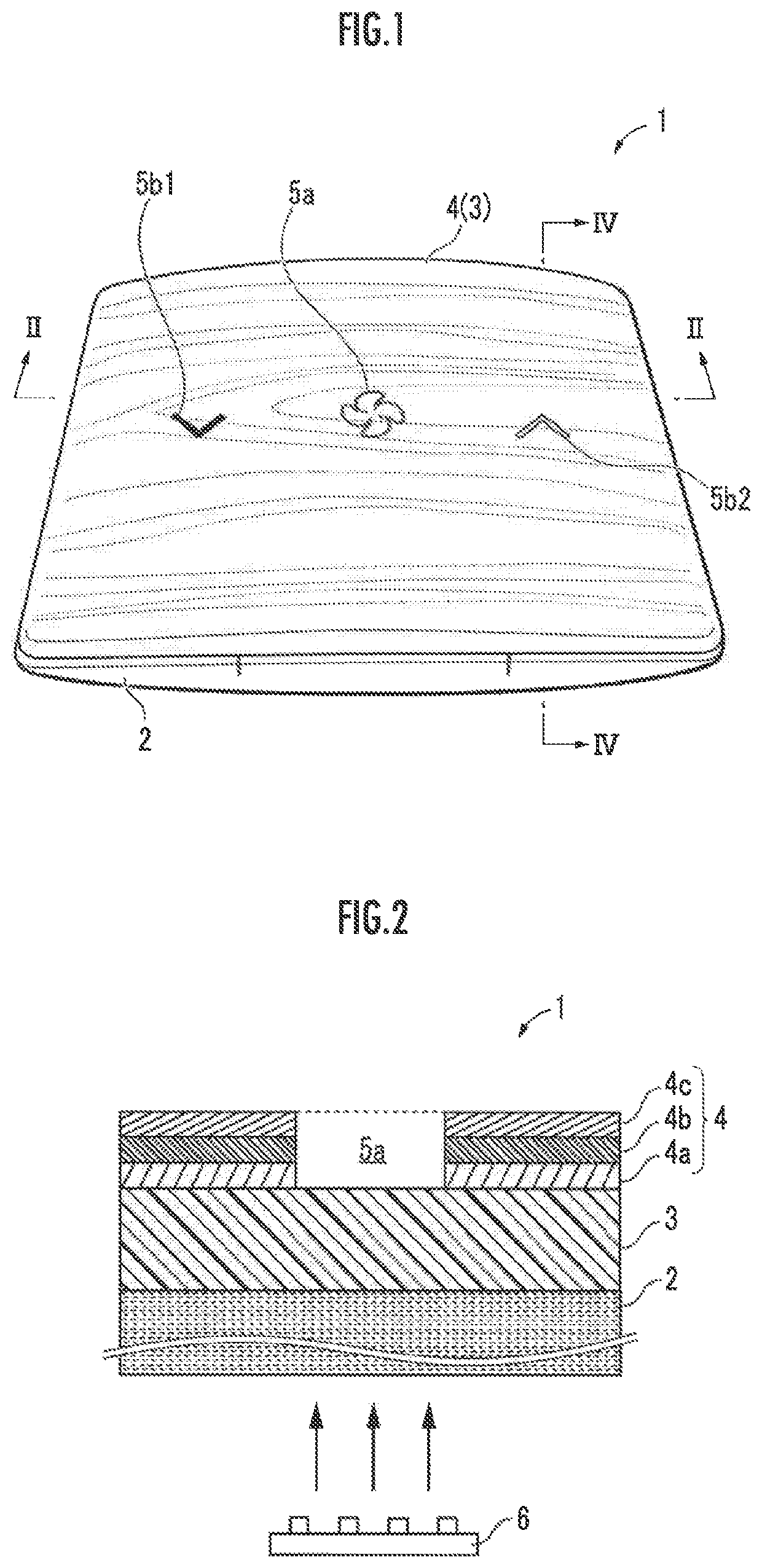
[0029]FIG. 1 is an overall structure of a panel element according to an aspect of the present invention. A panel element 1 is manufactured by so-called film insert molding, in which a decoration is printed on at least a front side of a resin sheet 3, and then pressure is applied to the resin sheet 3 to integrate the resin sheet 3 with a molded resin portion 2. The panel element 1 is used, for example, as an interior decorative part for a vehicle.

[0030]The molded resin portion 2 is a plastic plate element having a thickness of about 3 mm, and a shallow recess matching the shape of the resin sheet 3 after a forming process is formed on a surface of the molded resin portion 2. In addition, a back surface of the molded resin portion 2 has a side plate having a height of about 15 mm so as to house a light source (LED substrate) which will be described below. The molded resin p...


PUM

PropertyMeasurementUnit
thicknessaaaaaaaaaa
thicknessaaaaaaaaaa
heightaaaaaaaaaa

Abstract

A method for manufacturing the panel element (1) according to an aspect of the present invention includes: a process of printing a printed layer (4a) formed of an ink that does not transmit light on a front side of a resin sheet (3); a process of superimposing and printing a printed layer (4b) on an upper surface of the printed layer (4a) to form a laminated printed layer (4); and a process of irradiating the laminated printed layer (4) with laser light on a front side thereof to remove a part of the laminated printed layer (4) and to form a hole portion having a vertical end face in the laminated printed layer (4).

Description

BACKGROUNDTechnical Field[0001]The present invention relates to a method for manufacturing a panel element used for an into decorative part for a vehicle or the like.Related Art[0002]Currently, for an interior decorative part for a vehicle or the like, a panel element having a surface to which a woodgrain tone or carbon tone design is applied and being illuminated with light from an internal light source is used. Screen printing, gravure printing, offset printing, and the like are well known as a method for printing such a design.[0003]For example, an illumination cover element of JP 2014-44375 A described below is a bezel constituting a start button of an engine of an automobile, and a metal tone decorative portion having metallic gloss is disposed over the entire periphery on a front side of a panel element. In the metal tone decorative portion, three illumination portions including characters of “OFF”, “ACC”, and “ON” are displayed. That is, the illumination cover element is conf...

Claims


Application Information

Patent Timeline
Patent Type & Authority Patents(United States)
IPC IPC(8): B41M7/00B41M1/30
CPCB41M1/30B41M7/0081B41P2200/40G09F13/08B41M3/06B41M5/24B44F1/066
Inventor GOTO, YOSHIHIDESAKUMA, KENSHI
Owner SANWA SCREEN
Why Eureka
Try Eureka