Unlock instant, AI-driven research and patent intelligence for your innovation.
Bicycle hub assembly
Active Publication Date: 2020-05-19
SHIMANO INC
View PDF10 Cites 2 Cited by
Summary
Abstract
Description
Claims
Application Information
AI Technical Summary
This helps you quickly interpret patents by identifying the three key elements:
Problems solved by technology
Method used
Benefits of technology
Benefits of technology
The invention is about a lock mechanism for bicycle hub assemblies that prevents the inner race of the bearing unit from rotating relative to the hub axle. By using a lock member with a threaded portion that is screwed to the axle threaded portion of the hub axle, the flexibility of material selection for the axially extending part is increased. The technical effect is to improve the reliability and performance of bicycle hub assemblies.
Problems solved by technology
Secondly, the bearing threaded portion of the inner race is screwed to the axle threaded portion of the hub axle by rotating the tool engagement member.
Secondly, the bearing threaded portion of the inner race is screwed to the axle threaded portion of the hub axle by rotating the inner race body with the axially extending part.
Method used
Image
Click on the blue label to locate the original text in one second.
Reading with bidirectional positioning of images and text.
Examples
first embodiment
[0080]
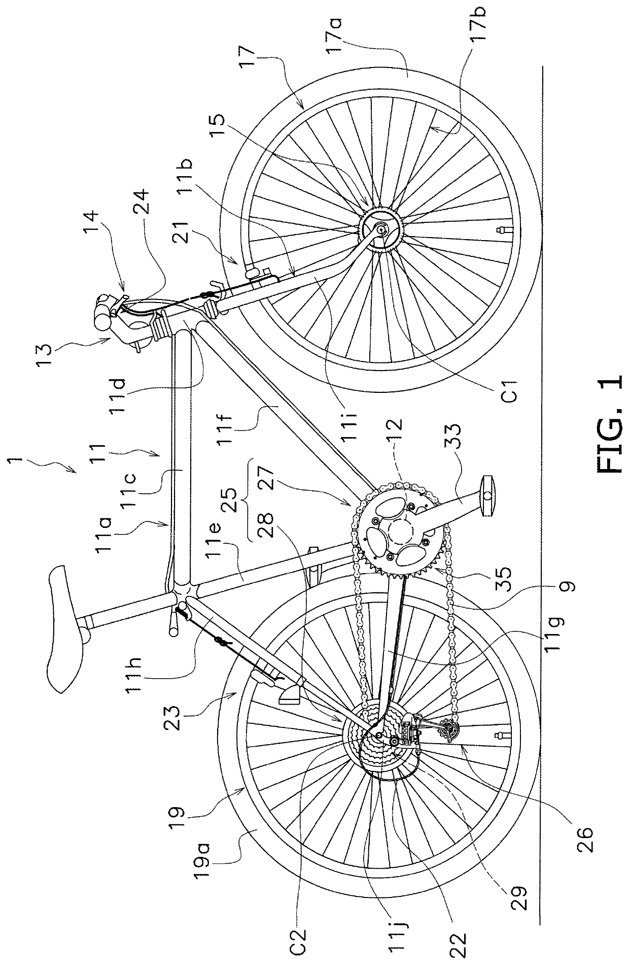
[0081]As shown FIG. 1, a bicycle 1 includes a bicycle chain 9, a frame 11, a handle 13, a front hub assembly 15 (an example of a bicycle hub assembly), front and rear wheels 17, 19, front and rear brake devices 21, 23, a shifting device 24, and a driving system 25.
[0082]The frame 11 includes a frame body 11a. The frame body 11a includes a top tube 11c, a head tube 11d, a seat tube 11e, a down tube 11f, a pair of chain stays 11g, a pair of seat stays 11h, and a bottom bracket hanger 12. A connection portion of the seat stay 11h and the chain stay 11g is described as a rear end 11j below.
[0083]A front fork 11b is rotatably attached to the head tube 11d of the frame body 11a. The front fork 11b includes a pair of leg portions 11i. Distal ends of the pair of leg portions 11i are described as a pair of front end 11k. The handle 13 is fixed to the front fork 11b.
[0084]The front hub assembly 15 is mounted to the front fork 11b. Specifically, the front hub assembly 15 is mounted betw...
second embodiment
[0167]A configuration of a second embodiment is the substantially same as the configuration of the first embodiment, except for the configuration of the first lock member 56 of the first embodiment.
[0168]Explanation of the same configuration as the first embodiment is omitted in the second embodiment. The omitted configuration is equivalent to the configuration described in the first embodiment. About the same configuration as the first embodiment, the references of the first embodiment is indicated in the second embodiment.
[0169](Third Lock Member)
[0170]In the second embodiment, as shown in FIGS. 5 and 6, a third lock member 156 (an example of a lock member), which corresponds to the first lock member 56 of the first embodiment, is configured as follows.
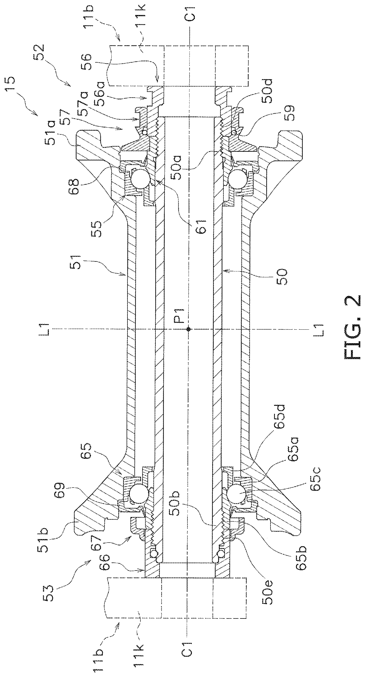
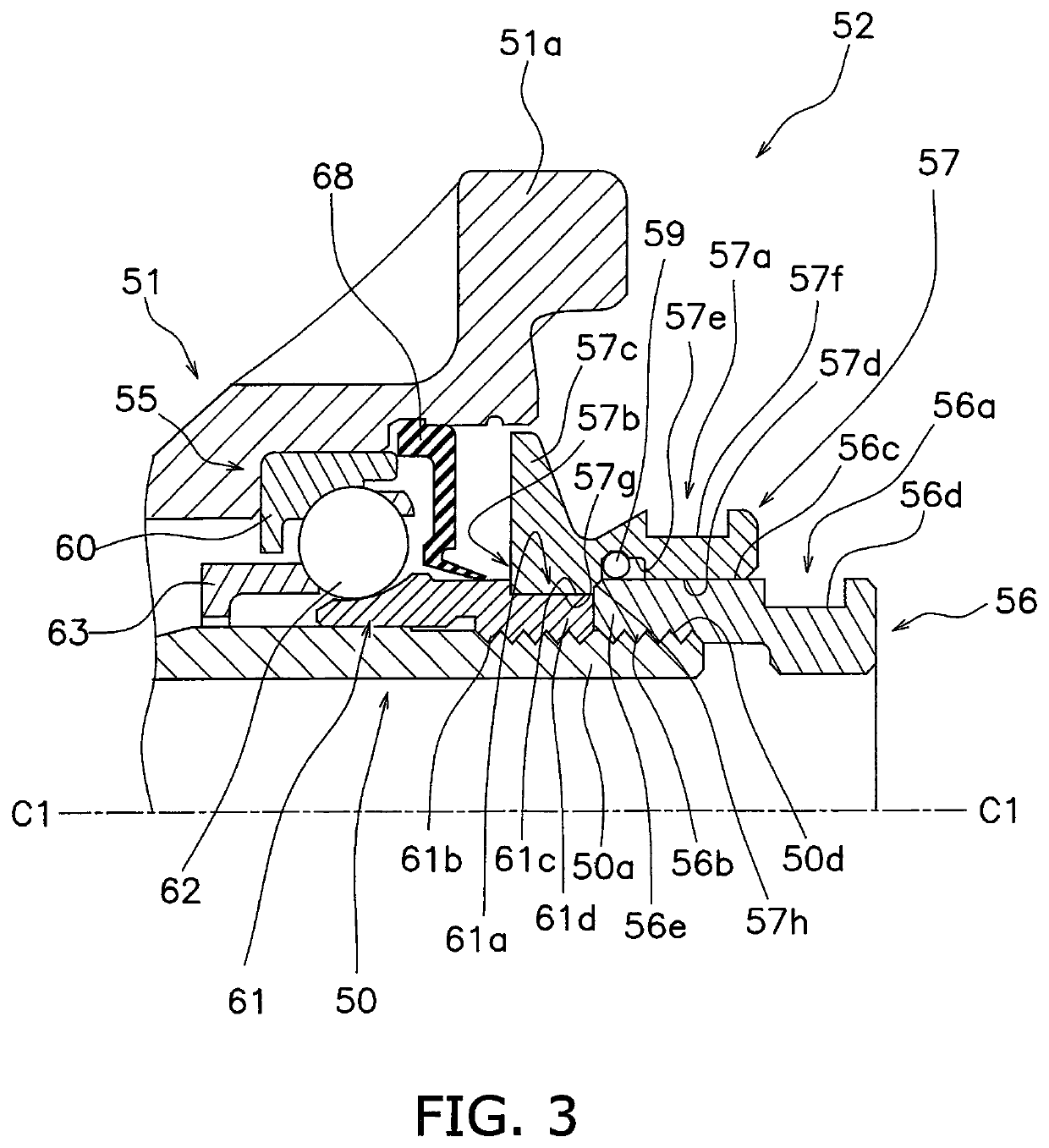
[0171]The third lock member 156 prevents the first inner race 61 of the first bearing unit 55 (see FIG. 2) from rotating relative to the hub axle 50 in a state where the first bearing unit 55 and the third lock member 156 are mounte...
PUM
Abstract
The bicycle hub assembly includes a hub axle, a hub body, a bearing unit, a lock member, and a tool engagement member. The bearing unit is configured to rotatably support the hub body around the hub axle with respect to the rotational center axis. The bearing unit includes an outer race, an inner race and a plurality of rolling members. The lock member prevents the inner race of the bearing unit from rotating relative to the hub axle. The tool engagement member is configured to rotate the inner race of the bearing unit relative to the hub axle.
Description
BACKGROUND[0001]Technical Field[0002]The technology disclosed herein relates to a bicycle hub assembly.[0003]Background Information[0004]A bicycle wheel typically includes a bicycle hub assembly. The bicycle hub assembly is located in the center of the bicycle wheel.[0005]A conventional bicycle hub assembly (e.g. U.S. Pat. No. 6,976,791 B2) includes a hub axle (10), a hub body (11), a bearing unit (13), and a lock member (15, 17). The hub axle (10) is mounted to a bicycle frame. The hub body (11) is rotatably supported around the hub axle (10) via the bearing unit (13). The bearing unit (13) is disposed between the hub axle (10) and the hub body (11).[0006]The bearing unit (13) includes an outer race, an inner race (32) and a plurality of rolling members. The outer race is mounted to an inner peripheral surface of the hub body (11). The inner race (32) is disposed inside the hub body (11) in a radial direction and is threadably mounted to an outer peripheral surface of the hub axle ...
Claims
Application Information
Patent Timeline
Application Date:The date an application was filed.
Publication Date:The date a patent or application was officially published.
First Publication Date:The earliest publication date of a patent with the same application number.
Issue Date:Publication date of the patent grant document.
PCT Entry Date:The Entry date of PCT National Phase.
Estimated Expiry Date:The statutory expiry date of a patent right according to the Patent Law, and it is the longest term of protection that the patent right can achieve without the termination of the patent right due to other reasons(Term extension factor has been taken into account ).
Invalid Date:Actual expiry date is based on effective date or publication date of legal transaction data of invalid patent.

