
Device for projecting a projectile by compressed air using electromagnetic piston compression, associated control method

a technology of electromagnetic piston and projectile, which is applied in the direction of compressed gas guns, white arms/cold weapons, weapons, etc., can solve the problems of high power at the beginning of the thrust and fade at the end of the thrust, and the possible number of shots is limited

Active Publication Date: 2020-05-26
TOKYO MARUI
View PDF10 Cites 1 Cited by
  • Summary
  • Abstract
  • Description
  • Claims
  • Application Information

AI Technical Summary

Benefits of technology

The patent text describes a need for a mechanism that combines the benefits of electrical energy to reduce consumption and increase the capacity of a replica weapon, while also minimizing or eliminating vibrations, impacts, and noise. The goal is to improve efficiency and stealth while also providing better power and performance. The invention aims to overcome the limitations of existing mechanisms and offer control over the projection device.

Problems solved by technology

These reserves may be of different sizes, but one of the problems is bulk.
Either the volume is sufficient but the pressurized container is bulky, or cartridges of small volume are used but the possible number of shots is limited.
It is also necessary to fill the pressurized container or to buy cartridges, which is not very satisfactory.
A spring has a major disadvantage: it releases a thrust that is irregular, with high power at the beginning of the thrust and fading at the end of its travel.
Finally, the electromechanical means consume large amounts of energy, particularly due to friction.
Similarly, the release of the spring / piston as well the stopping of the spring / piston at the end of travel leads to an evident lack of flexibility, affecting the accuracy of the shot to say nothing of the discomfort for the shooter.

Method used


Image

  • Device for projecting a projectile by compressed air using electromagnetic piston compression, associated control method
  • Device for projecting a projectile by compressed air using electromagnetic piston compression, associated control method
  • Device for projecting a projectile by compressed air using electromagnetic piston compression, associated control method

Examples


Embodiment Construction

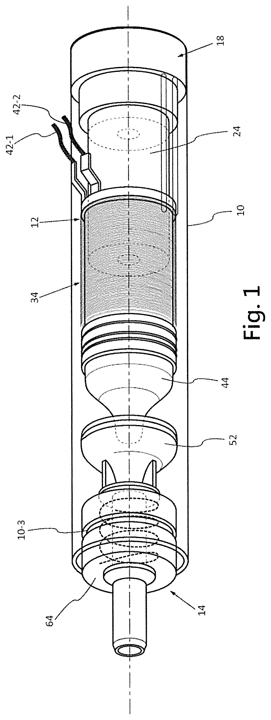
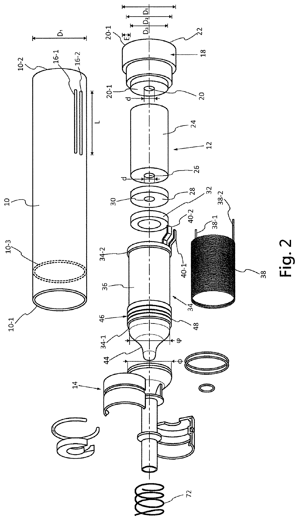
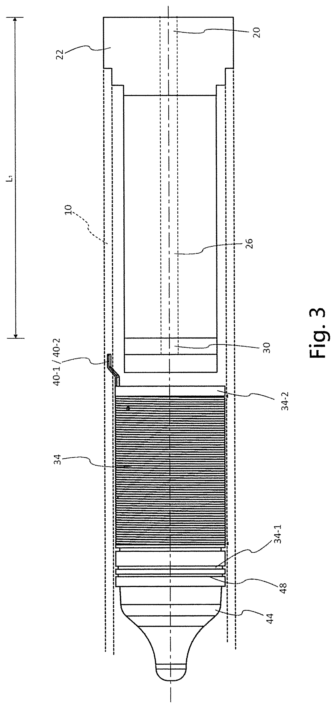
[0036]The invention is now described with reference to FIGS. 1 and 2, in order to define the component parts of the electromagnetic projection device according to the invention.

[0037]These various components are designed to be integrated into a housing that can be a replica weapon. This replica weapon comprises at least one barrel for guiding the projectile launched by the projection device according to the invention.

[0038]A source of electrical energy, not shown, must be associated with the projection device of the invention to enable it to operate, said source not being part of the invention and remaining within the reach of those skilled in the art.

[0039]In these figures, a sheath 10 is represented which receives movable electromagnetic means 12 and a thrust nose 14.

[0040]The sheath 10 has a cylindrical inner shape of diameter D1. Preferably the sheath material is soft iron with very low carbon content or an iron / cobalt alloy.

[0041]Near the front end 10-1 of the sheath, an annula...


PUM


Abstract

The invention relates to a device for projecting a projectile B using a compressed air, in particular provided to be built into a replica weapon, associated with a source of electrical energy. The device comprises a sheath (10) which receives an electromagnetic means (12) for moving a movable piston (34) within the sheath (10) between a thrust nose (14) sealing a front (10-1) of the sheath provided with a projection tube, and a breech (18) sealing a rear (10-2) of the sheath. The invention also relates to a method for controlling the device.

Description

CROSS-REFERENCE TO RELATED APPLICATION[0001]This application is a 371 application of the international PCT application serial no. PCT / EP2016 / 078034, filed on Nov. 17, 2016, which claims the priority benefit of France application no. 1561055, filed on Nov. 17, 2015. The entirety of each of the above-mentioned patent applications is hereby incorporated by reference herein and made a part of this specification.TECHNICAL FIELD[0002]The present invention relates to a device for projecting a projectile using compressed air which is compressed by an electromagnetic piston.[0003]The invention also covers a method for controlling the device for projecting using compression by electromagnetic piston.BACKGROUND ART[0004]The recreational sport referred to as “Airsoft” is known, which consists of using replica weapons and projectiles for team games.[0005]The power of the projectiles is limited in order to remain within the field of recreational and competitive sports games.[0006]Many arrangement...

Claims


Application Information

Patent Timeline
Patent Type & Authority Patents(United States)
IPC IPC(8): F41B11/64F41B6/00
CPCF41B6/003F41B11/64
Inventor LEMARQUAND, GUY
Owner TOKYO MARUI
Learn More