Method of imaging motion of an organ

a technology of organ motion and imaging method, applied in the field of imaging, can solve the problems of poor temporal resolution of ct, inability to detect changes using conventional two-dimensional x-ray imaging, and limitation of the use of dynamic lung tes

Active Publication Date: 2020-06-09
4DMEDICAL LTD
View PDF67 Cites 1 Cited by
  • Summary
  • Abstract
  • Description
  • Claims
  • Application Information

AI Technical Summary

Benefits of technology

[0028]Another object of the present invention is to provide improved technology for obtaining data of lung motion.
[0075]One embodiment of this technique aims to cluster the images into each projection, by taking multiple images from each view. This then allows for a calculation of motion from each aforesaid view and therefore a reconstruction of the full 4D motion field of the lungs. Techniques for image reconstruction such as CT, 4DCT and 4DCBCT aim to distribute the projections evenly around the patient from a large number of views.

Problems solved by technology

These changes may not be detectable using conventional two-dimensional X-ray imaging.
One of the principal limitations of these approaches is the need to image the lung while it is stationary in order to minimise blurring.
In particular, CT has poor temporal resolution limiting its use for a dynamic lung test.
This has obvious drawbacks and limits the ability of CT to be used for dynamic lung function testing.
They cannot produce continuous real-time images that would provide information regarding lung motion and be used to detect diseases that cause subtle changes in lung structure or function.
For example, 4D-CT has been used for measurement of lung function, including expansion using traditional absorption based imaging, but has the drawback of delivering significant levels of radiation dose to the patient.
Motion of cancers causes problems with irradiation treatment because moving targets may appear with distorted shapes and in wrong locations on CT images.
An important issue within radiology today is how to reduce the radiation dose during CT scanning without compromising the image quality.
In general, higher radiation doses result in higher-resolution images, while lower doses lead to increased image noise and blurred images.
However, higher radiation doses increase adverse side effects, including the risk of radiation induced cancer.
Notwithstanding these efforts, the relatively high radiation dose imposed on a patient by a CT scan (especially by a 4D-CT scan), is a key problem acting against the increased use of CT.
If the sample displacement is too large or too small, the measurement quality will be degraded.
Imaging of samples that exhibit a large range of speeds during the measurement sequence using a constant acquisition rate will therefore inevitably cause degraded measurement quality for some of the frames.
When using X-ray images as the input, techniques such as these result in an increase in radiation dose imparted to the subject as extra (redundant) images are acquired.

Method used


Image

  • Method of imaging motion of an organ
  • Method of imaging motion of an organ
  • Method of imaging motion of an organ

Examples


Embodiment Construction

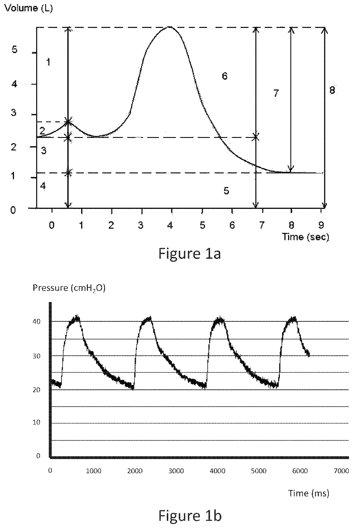
[0086]FIG. 1a is a plot of lung volume (litres) versus time (sec) during inspiration and expiration of a human lung. The plot illustrates inspiratory reserve volume (IRV) 1, VT 2, expiratory reserve volume (ERV) 3, residual volume (RV) 4, functional reserve capacity (FRC) 5, inspiratory capacity (IC) 6, vital capacity (VC) 7, total lung capacity (TLC) 8

[0087]FIG. 1b is a plot of pressure (cm / H2O) versus time (ms) for inspiration and expiration of a human lung. The flow of air into and out of the lung can be correlated with the change in volume of the lung as shown in FIG. 1a.

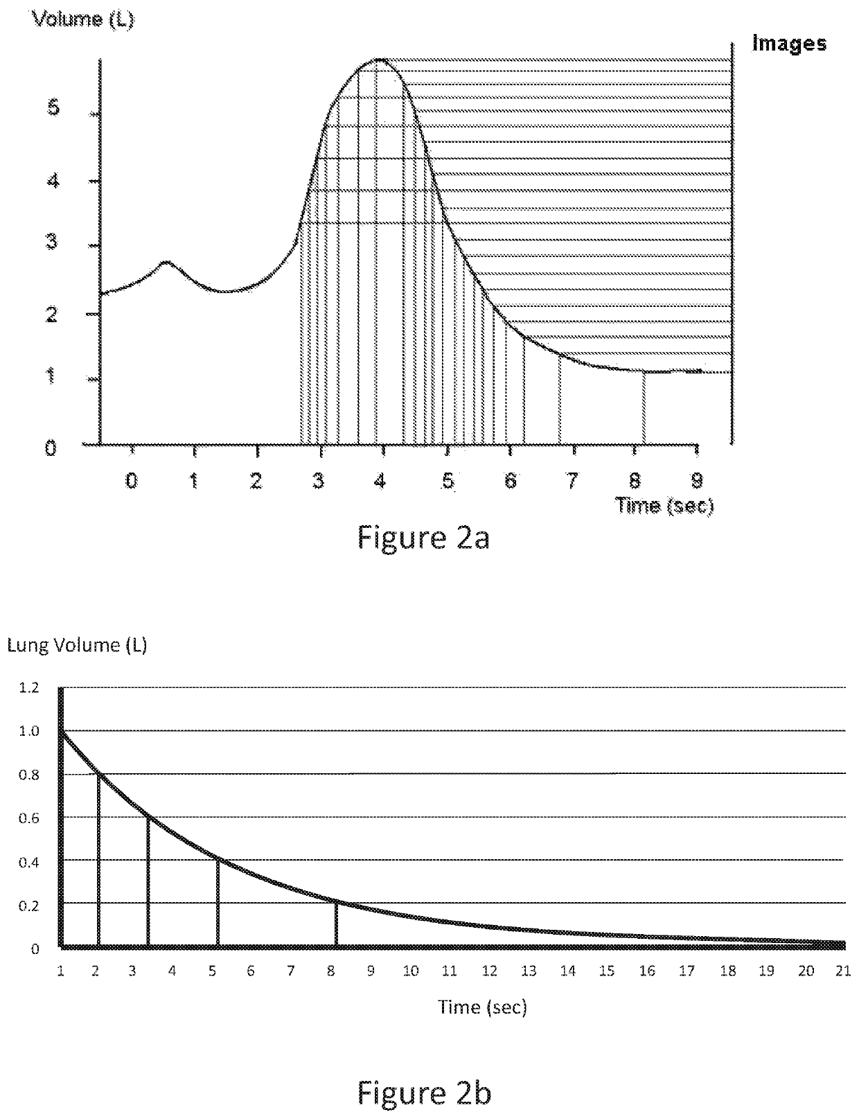
[0088]In the past, images of organs that change volume, such as the heart, blood vessels or lungs have been recorded at the fastest imaging rate possible with a constant time between images.

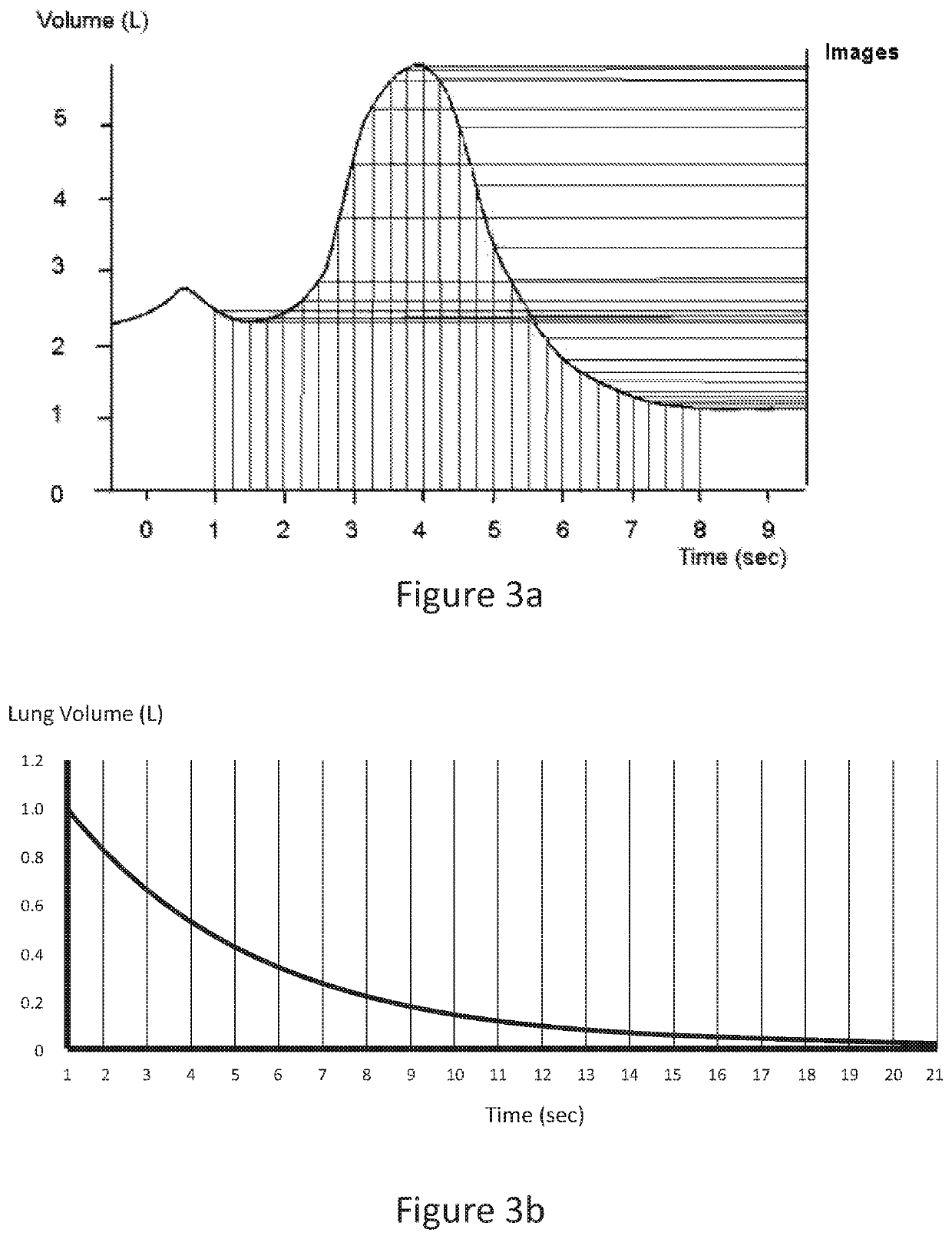
[0089]With reference to lungs, this was an attempt to capture the fast motion that occurs during the beginning of the inspiratory cycle and the beginning of the expiratory cycle. FIG. 3 is a plot of lung volume (litres) agai...


PUM


Abstract

A method of imaging motion of an organ that changes volume in a patient including the steps of monitoring change in volume of the organ, and recording multiple in vivo images of the organ, wherein the change of organ volume between the images is constant or of some other predetermined value.

Description

CROSS REFERENCE TO RELATED APPLICATIONS[0001]This application is a National Stage of International Application No. PCT / AU2015 / 000219 filed Apr. 14, 2015, claiming priority based on Australian Patent Application No. 2014901375 filed Apr. 15, 2014, the contents of all of which are incorporated herein by reference in their entirety.FIELD OF INVENTION[0002]The present invention relates to the field of imaging, particularly imaging of organs such as the lung.[0003]In one form, the invention relates to the field of imaging organs, such as the lung for diagnostic or research purposes.[0004]In one particular aspect the present invention is suitable for use as a technique for assessing organ motion.[0005]It will be convenient to hereinafter describe the invention in relation to human medical applications however, it should be appreciated that the present invention is not limited to that use only and could, for example, be used for veterinary applications.[0006]Furthermore, it will be also co...

Claims


Application Information

Patent Timeline
Patent Type & Authority Patents(United States)
IPC IPC(8): A61B6/00A61B8/08A61B5/055A61B5/00A61B6/03A61B6/02
CPCA61B8/08A61B5/055A61B8/5223A61B6/4085A61B6/5217A61B6/4014A61B5/7282A61B6/487A61B6/032A61B6/542A61B6/5288A61B6/541A61B6/02G16H50/30A61B6/022
Inventor FOURAS, ANDREAS
Owner 4DMEDICAL LTD
Why Eureka
Try Eureka