Installation for powering auxiliary equipment in electrical energy generation plants

a technology for auxiliary equipment and power generation plants, which is applied in the direction of pv power plants, emergency protective arrangements for limiting excess voltage/current, transportation and packaging, etc. it can solve the problems of high cost of this solution, the design of high-input voltage dc/dc converters is relatively complex, and the design of high-input voltage dc/dc converters

Active Publication Date: 2020-06-30
SOLTEC ENERGIAS RENOVABLES
View PDF4 Cites 0 Cited by
  • Summary
  • Abstract
  • Description
  • Claims
  • Application Information

AI Technical Summary

Benefits of technology

[0020]As far as the input terminals of the current-fed power converter, they can be removably connected, in one embodiment, to the cited two connection points of the DC-generating arrangement, and alternatively they can be connected to two other connection points thereof. This grants great flexibility when it comes to obtaining energy for auxiliary loads in any location of a DC or photovoltaic (PV) installation, for example.
[0022]Through the present invention, auxiliary electronics, i.e., auxiliary systems located in the local area where the electricity generation plant is located, can be powered, not by the voltage provided by all the generators arranged in series, but by the current circulating through them. This power supply method does not affect significantly the generation of any of the panels in particular, and access to the junction box is not required since the power converter is connected as if it were another panel; it will only be necessary to provide the power converter with connectors similar to those of the panels, which would in turn facilitate installation. The voltages supported by the components of the power converter will be of the order of the voltage at its output (possibly 24 / 48 V), so the components of the power converter have a lower cost than the components used in conventional proposals. Furthermore, current feeding can be done from any point by opening the row of generators or the string, wherever necessary, usually in the area closer to the auxiliary systems, so as to reduce the need to lay cables as much as possible.
[0024]According to a preferred embodiment, the system for protection against overvoltages also comprises a control circuit for said switch, both working independently with regards to the current-fed power converter, since they are unable to use energy from the output of the power converter as they protect the latter from malfunctioning.

Problems solved by technology

However, the highest cost of this solution is possibly associated with laying the cables and channels of the low-voltage installation BT.
To that end, a DC / DC converter will be required that can withstand the open-circuit voltage of the installation, which in most cases will be close to 1000 V. This converter will have a relatively complex design and will require batteries to provide power peaks or supply energy in absence of the sun.
Another problem in this type of installation is the design of the high-input voltage DC / DC converter.
In any case, it is not a simple design, so it will increase the cost of manufacturing the converter.

Method used


Image

  • Installation for powering auxiliary equipment in electrical energy generation plants
  • Installation for powering auxiliary equipment in electrical energy generation plants
  • Installation for powering auxiliary equipment in electrical energy generation plants

Examples


Embodiment Construction

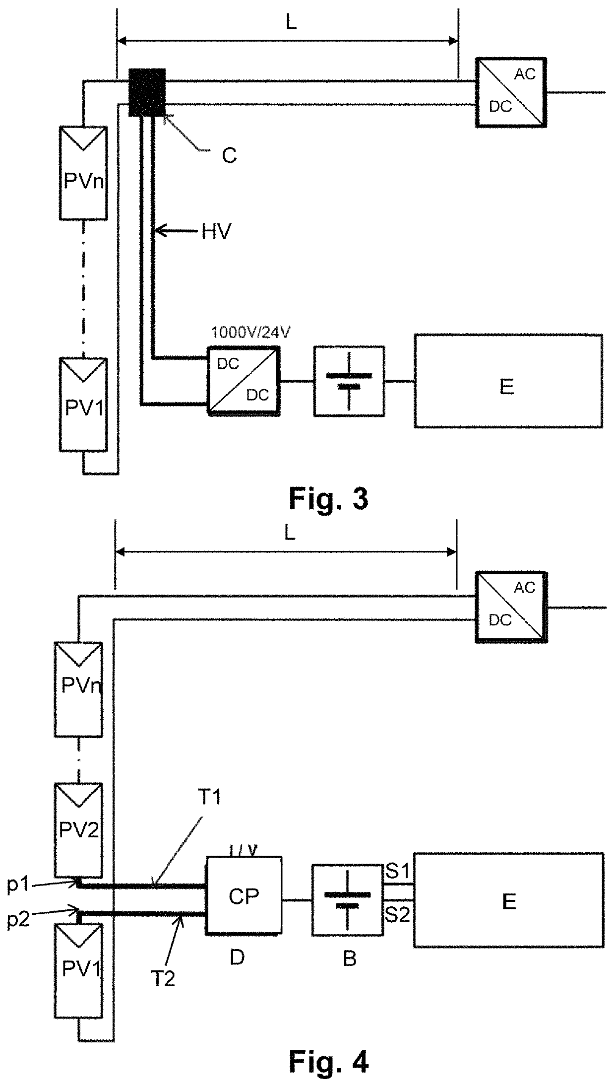
[0051]FIG. 4 shows an embodiment of the installation proposed by the present invention, for which it includes:[0052]a DC-generating arrangement made up of a plurality of generators or photovoltaic panels PV1 . . . PVn which are connected in series and located inside a local area, and envisaged to supply electrical energy to a remote area and specifically for providing a total direct current with a voltage that is the sum of the current generated by each of said generators or photovoltaic panels PV1 . . . PVn through end terminals of the DC-generating arrangement located in said remote area, which is located at a distance L of several tens or hundreds of meters; and[0053]an auxiliary power supply device D which is arranged inside the local area and provides the auxiliary systems E (in this case through a battery B) with a supply voltage in said local area, and said auxiliary power supply device D comprising a current-fed power converter CP electrically connected in series, respective...


PUM


Abstract

The installation comprises:a DC-generating arrangement formed by electrical generators (PV1 . . . PVn) which are connected in series and located inside a local area, and supply a remote area with a total direct current that is the sum of the current generated by each of the electrical generators (PV1 . . . PVn); andan auxiliary power supply device (D) which is arranged inside the local area and provides the auxiliary system (E) with a supply voltage in the local area, wherein the auxiliary power supply device (D) is made up of a current-fed power converter (CP) electrically connected in series, respective input terminals (T1, T2), in the DC-generating arrangement between two connection points (p1, p2) of the electrical generators, located inside the local area.

Description

TECHNICAL FIELD[0001]The present invention relates generally to the field of electricity generation installations located in a given local area and envisaged for supplying electrical energy to a remote area.[0002]Particularly, the present invention relates to an installation for powering auxiliary systems in electricity generation plants such as a solar farm or plant comprising an arrangement of a plurality of electrical generators (in the case of a solar farm, for example, there is one electrical generator per solar collector) connected in line, in series, supplying direct current to a remote area and with at least one auxiliary power supply device in said electricity generation plant intended for supplying a supply voltage to a device (for example, a battery or battery bank) of said local area; and more particularly, the present invention relates to an installation in which the mentioned auxiliary power supply device comprises a current-fed power converter connected in series with...

Claims


Application Information

Patent Timeline
Patent Type & Authority Patents(United States)
IPC IPC(8): H02S40/32H02J3/38H02S10/00H02S40/30H02H9/04H02J7/00
CPCH02S40/32H02H9/041H02S40/30H02S10/00H02J3/38H02J7/00H02J2300/24H02J3/381Y02E10/56
Inventor FERNANDEZ LUQUE, FRANCISCO JESUSVILLAREJO MANAS, JOSE ANTONIO
Owner SOLTEC ENERGIAS RENOVABLES
Why Eureka
Try Eureka