
Fluoride trapping arrangement

a technology of fluoride and trapping arrangement, which is applied in the direction of amphoteric ion exchangers, sugar derivative introduction of isotopes, chemical/physical processes, etc., can solve the problems of not being able to fit all the duplicate components for a second batch onto the same cassette, and not being able to carry out back to back runs of the above-described process on the same apparatus, etc., to achieve good trapping and elution, good yield

Active Publication Date: 2020-07-07
GE HEALTHCARE LTD
View PDF17 Cites 1 Cited by
  • Summary
  • Abstract
  • Description
  • Claims
  • Application Information

AI Technical Summary

Benefits of technology

[0040]The present invention permits good trapping and elution of two batches of incoming [18F]fluoride activity, and good yields for the production of two batches of [18F]-labelled compound. Using the system of the present invention two batches of [18F]-fluoride can be trapped and [18O]water recovered using fewer positions than for previous systems, thereby making a position on the cassette available for the placement of another component. So, for example it is possible to place reagent vials for both ethanol and acetonitrile, in contrast to the prior art single-run cassettes that have either ethanol or acetonitrile rather than both, and the dual-run cassette described in WO2015071288 where only acetonitrile is available. Ethanol can be used in the conditioning of SPE columns, in the cleaning steps between first and second batches, and can be used as a radiostabilizer if desired. As described in Example 1 below for [18F]FDG synthesis, reversed-phase purification column of an exemplary system of the present invention can be rinsed between runs with ethanol and water independently of the alumina column such that there is a negligible amount of Kryptofix™ 222 in the both batches of [18F]labelled compound, thereby providing an advantage over WO2015071288 where the second batch has a higher concentration. Acetonitrile is the ideal drying solvent to remove water effectively during evaporation processes and can also be used in conditioning of SPE columns Having both solvents available is advantageous therefore in terms of flexibility of the process used.
[0041]Also, the configuration of the present invention allows an enriched water recycling pathway only on the left side of the cassette for both FDG batch (FIG. 5) (avoid contamination of the manifold with water and of the enriched water with residual organic solvents) with only six positions (the activity inlet, position 1 with the connection of enriched water vial, position 4 for the QMA 1, position 5 for tubing of QMA 2, position 7 for tubing of QMA 1 and position 8 for the QMA 2) on the cassette engaged.

Problems solved by technology

However, because of the residual activity on the FASTlab™ cassette, transfer line and the shadow from the waste bottle after completion of a batch, it is impossible for safety reasons to carry out back to back runs of the above-described process on the same apparatus.
Furthermore, it is only possible to fit one FASTlab™ apparatus in a hot cell.
With only 2 positions to spare, it is not possible to fit all the duplicate components for a second batch onto the same cassette.
Recycling the QMA column to use in a second batch presents a particular challenge because a salt solution is required for cleaning.
Furthermore, a salt solution is undesirable because it can contaminate the rest of the manifold as the salt solution must be withdrawn using a syringe and then passed through the cassette and collected to the waste at the other side of the cassette.
However, the present inventors have found problems with this configuration; firstly contamination of the manifold with enriched water is possible because of the pathway taken for enriched water recovery to the right of the manifold for the second batch.
This is a risk for the second labelling reaction.
Also, as a consequence of using up seven positions for the QMA arrangement there are limited options for placement of the other components.
In particular, the Oasis HLB purification column is directly connected to the alumina column so that there is no way to properly clean the Oasis HLB after the first batch because of the risk of contaminating the alumina column with organic solvent.
As a result, there is a risk that non-negligible amounts of Kryptofix 2.2.2 will be present in the final product from the second batch.

Method used


Image

  • Fluoride trapping arrangement
  • Fluoride trapping arrangement
  • Fluoride trapping arrangement

Examples


example 1

of Two Batches of [18F]FDG on One FASTlab Cassette According to an Embodiment of the Present Invention

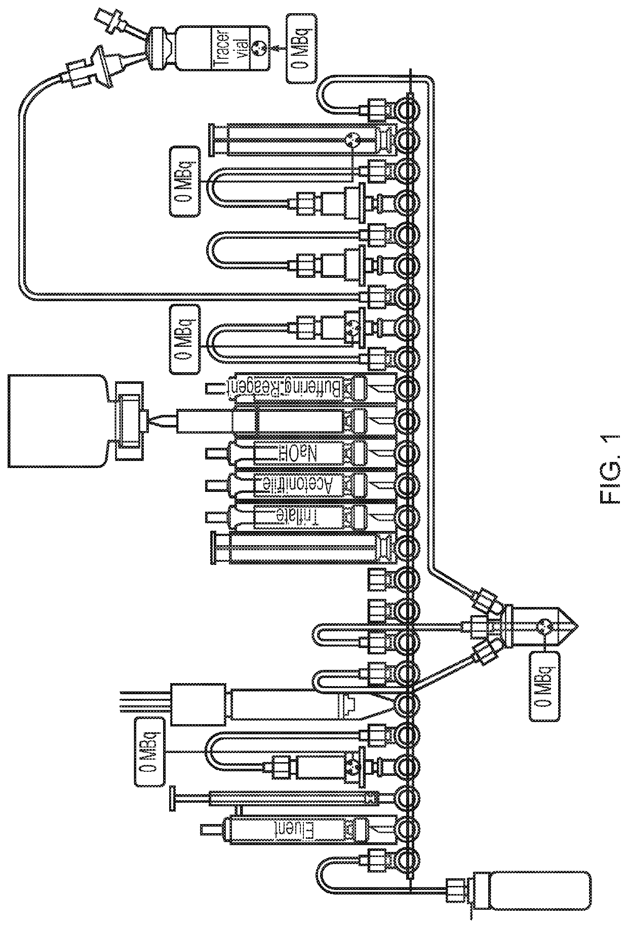
[0079]The cassette configuration as illustrated in FIG. 5 was used in this Example.

(1) The tC18 environmental at position 18 was conditioned with 800 μL MeCN from the reagent vial at position 15 and the tC18 plus column at position 22 was conditioned with 1.5 mL EtOH from the reagent vial at position 12.

(2) [18F]-fluoride was obtained from the bombardment of [18O]—H2O with a high-energy proton beam extracted from a cyclotron (Cyclotron Cyclone 18 / 9 from IBA) and transferred to the FASTlab cassette via the conical reservoir at position 6.

(3) [18F]Fluoride was trapped on the QMA column at position 4 and separated from the enriched water which was collected in an external vial via a V7-V4-V1 pathway.

(4) Eluent was withdrawn in the syringe at position 3 and passed through the QMA column at position 4 to release [18F]fluoride and send to the reaction vessel.

(5) Evaporation of the water f...


PUM

PropertyMeasurementUnit
temperatureaaaaaaaaaa
lengthaaaaaaaaaa
rigid polymericaaaaaaaaaa

Abstract

The present invention provides a new chemical process, a new cassette configuration, and new software for the automated production of multiple batches of an [18F]labelled compound on a single cassette. The invention allows one synthesizer in one hot cell to produce sequentially a plurality of batches of [18F]-labelled PET tracer in the same day. In particular, the present invention provides a novel arrangement useful for the trapping of [18F]fluoride and recovery of [18O]water.

Description

TECHNICAL FIELD OF THE INVENTION[0001]The present invention concerns devices and methods for the automated synthesis of [18F]-labelled compounds, in particular those suitable for use as in vivo imaging agents for positron emission tomography (PET). The focus of the present invention is for the automated synthesis of more than one batch of an [18F]-labelled compound using just one disposable cassette and in particular a novel system for trapping and elution of [18F]fluoride.DESCRIPTION OF RELATED ART[0002]Radiolabelled compounds for use as in vivo imaging agents are currently typically prepared by means of an automated synthesis apparatus (alternatively “radiosynthesizer”). Such automated synthesis apparatuses are commercially available from a range of suppliers, including: GE Healthcare; CTI Inc.; Ion Beam Applications S.A. (Chemin du Cyclotron 3, B-1348 Louvain-La-Neuve, Belgium); Raytest (Germany) and Bioscan (USA). The radiochemistry takes place in a “cassette” or “cartridge” des...

Claims


Application Information

Patent Timeline
Patent Type & Authority Patents(United States)
IPC IPC(8): C07B59/00C07H5/02B01J41/09A61K51/04B01D15/14B01D15/18B01D15/36B01D15/42B01J41/04B01J41/20B01J47/022C07H1/06
CPCC07H1/06B01D15/363A61K51/0497B01D15/14B01J47/022B01D15/1885C07B59/00B01D15/424B01J41/04C07H5/02B01J41/09B01J41/20C07B2200/05C07B59/005A61K51/04
Inventor FRANCI, XAVIERLIGNON, STEVELANGE, AUDREY MARIEVERBRUGGE, NICOLAS
Owner GE HEALTHCARE LTD
Learn More