Laser sensor and manufacturing method for exterior component

a technology of laser sensor and manufacturing method, which is applied in the direction of electromagnetic wave reradiation, measurement devices, instruments, etc., can solve the problems of dustproof and waterproof properties of exterior components, optical window accuracy, and possible defects, and achieve excellent dustproof and waterproof properties, high rigidity, and shape variation

Active Publication Date: 2020-07-07
KONICA MINOLTA INC
View PDF16 Cites 2 Cited by
  • Summary
  • Abstract
  • Description
  • Claims
  • Application Information

AI Technical Summary

Benefits of technology

[0010]In the above-described laser sensor, since the optical window and the holder of the exterior component are formed as the integrally-molded product made of the resin, excellent dustproof and waterproof properties can be achieved because there is no need to join the optical window to the holder in a separate step. Furthermore, since the optical window and the holder are integrated, the exterior component of the laser sensor has relatively high rigidity, shape variation due to shrinkage and deformation at the time of molding is reduced, and the optical window with high accuracy is achieved. Moreover, since the optical window and the holder are integrated, structural or shape-related restrictions are more reduced than in the case of joining the optical window in a separate step, and weight reduction and miniaturization of the laser sensor can be achieved.
[0012]In the manufacturing method for an exterior component, since the optical window and the holder of the exterior component are integrally molded by using the resin, excellent dustproof and waterproof properties can be achieved because there is no need to join the optical window to the holder in a separate step. Additionally, since the optical window and the holder are integrated, the exterior component has relatively high rigidity, shape variation due to shrinkage and deformation at the time of molding is reduced, and the optical window with high accuracy is achieved. Furthermore, since the optical window and the holder are integrated, structural or shape-related restrictions are more reduced than in the case of joining the optical window in a separate step, and weight reduction and miniaturization of the exterior component can be achieved. Moreover, since the gate is provided at the position relatively distant from the window transfer, it is possible to suppress deformation of a surface shape of the optical window due to distortion of the gate part at the time of molding.

Problems solved by technology

When the exterior component is manufactured by the above-described method, there are problems in accuracy of the optical window, dustproof and waterproof properties of the exterior component, weight reduction, and miniaturization.
First, as for the accuracy of the optical window, in a case where the optical window has a curved surface, there is a problem that a manufacturing error such as a shape error at the time of bending processing and a thickness error at the time of injection molding are likely to occur.
Additionally, when the optical window is joined to a component to which the optical window is to be attached by using an adhesive or the like, there is a problem that the surface shape of the optical window is likely to be distorted by stress.
Thus, when accuracy of the optical window is not good, a light amount is reduced because the laser cannot be projected and received at an aimed place, and there is a possibility that detection accuracy is seriously deteriorated, especially on a long-distance side.
Additionally, as for the dustproof and waterproof properties, in a case where the optical window is made of a resin and a component to which the optical window is to be attached is made of a metal, there is a problem that a joined part is easily peeled off due to a difference in linear expansion, and dust and moisture intrude in the inside at the time of environment change such as change of a temperature or the like.
Furthermore, as for the weight reduction and miniaturization, restrictions are imposed on matters such as components to be joined and a joining range in view of securing strength and the like, and there may be a problem that application to a compact moving body such as a drone becomes difficult.

Method used


Image

  • Laser sensor and manufacturing method for exterior component
  • Laser sensor and manufacturing method for exterior component
  • Laser sensor and manufacturing method for exterior component

Examples


first embodiment

[0025]A laser sensor and a manufacturing method for an exterior component therefor according to an embodiment of the present invention will be described below with reference to the drawings.

[0026][Laser Sensor]

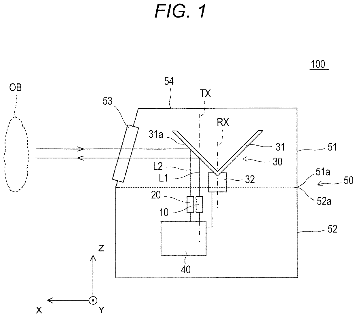
[0027]FIG. 1 illustrates a schematic structure of a laser sensor 100 according to a first embodiment of the present invention. The laser sensor 100 is, for example, an object detection device used for indoor / outdoor monitoring or used for an on-vehicle application, and detects presence of a detection object and a distance to the detection object. The laser sensor 100 includes a light projector 10, a light receiver 20, a rotating reflector 30, a controller 40, and an exterior component 50. In the present embodiment, the light projector 10, light receiver 20, rotating reflector 30, and controller 40 are provided inside an exterior component 50 as built-in components of the laser sensor 100.

[0028]In the laser sensor 100, the light projector 10 projects laser light L1 to a reflect...

second embodiment

[0056]A manufacturing method and the like for an exterior component according to a second embodiment will be described below. The manufacturing method and the like for an exterior component according to the second embodiment is a method obtained by partly modifying a manufacturing method for an exterior component according to a first embodiment, and matters not specifically described are similar to those in the first embodiment.

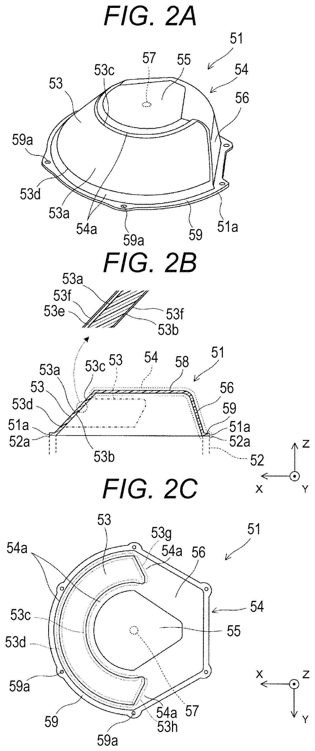
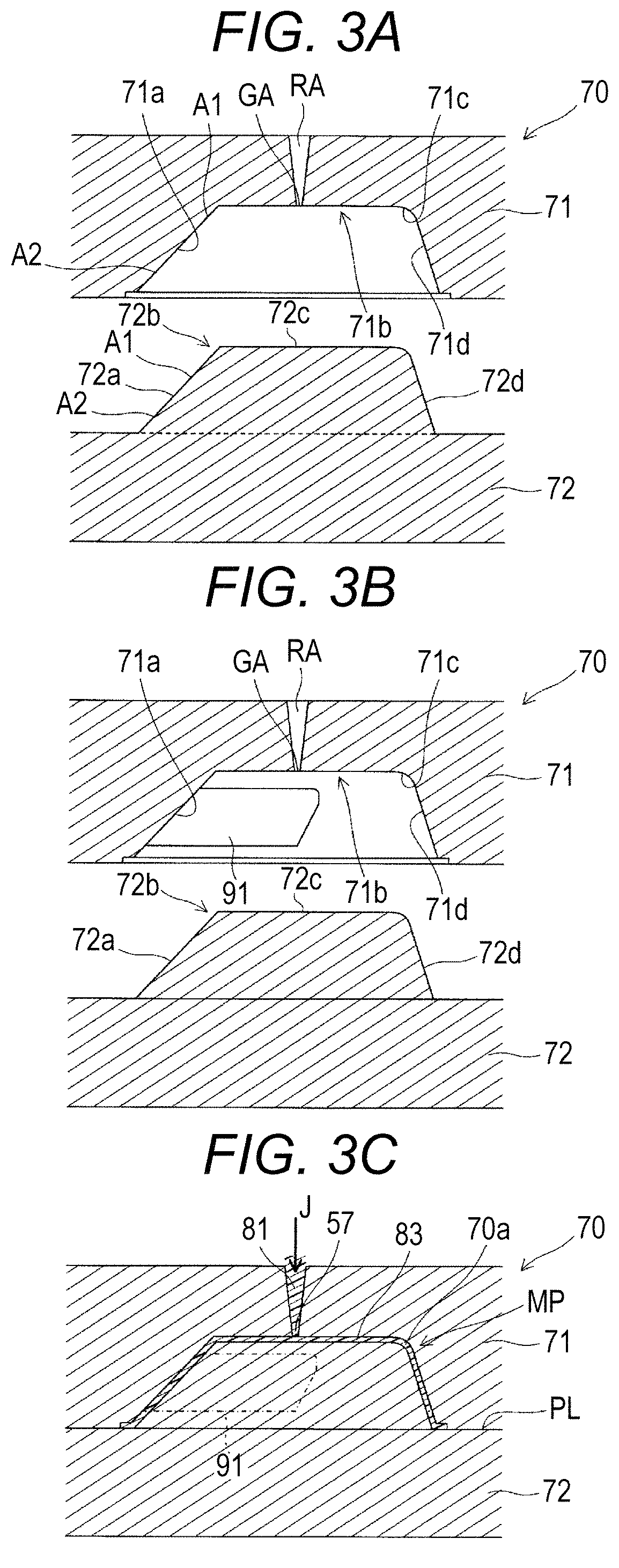
[0057]As illustrated in FIG. 6, a first metal mold 71 is a movable metal mold and a second metal mold 72 is a fixed metal mold in a metal mold 70 used to manufacture an exterior component 50 of the present embodiment. In other words, a structure of the metal mold 70 described in the first embodiment is reversed, and a gate GA is provided on the second metal mold 72 side. Therefore, in a main exterior part 51 to be molded, the gate part 57 is formed substantially at a center of a rear side surface of a lid part 55 of a holder 54.

third embodiment

[0058]A manufacturing method and the like for an exterior component according to a third embodiment will be described below. The manufacturing method and the like for an exterior component according to the third embodiment is a method obtained by partly modifying a manufacturing method for an exterior component according to a first embodiment, and matters not specifically described are similar to those of the first embodiment.

[0059]The manufacturing method for an exterior component according to the present embodiment will be described below. In the first embodiment, a molding step and a hard coat treatment step are performed in parallel, but in the present embodiment, the hard coat treatment step is performed after the molding step.

[0060]A) Molding Step

[0061]First, as illustrated in FIG. 7A, a metal mold 70 similar to that of the first embodiment is prepared, and the first and second metal molds 71 and 72 are clamped and a molten resin J is injected into a molded space 70a as illust...


PUM

PropertyMeasurementUnit
irradiation angleaaaaaaaaaa
wavelength bandaaaaaaaaaa
angleaaaaaaaaaa

Abstract

Provided is a laser sensor including an optical window with high accuracy and having excellent dustproof and waterproof properties. The laser sensor includes: a light projector; a light receiver to detect reflection light from a detection object to which laser light is emitted from the light projector; and an exterior component covering the light projector and the light receiver, in which the exterior component includes an optical window that transmits the laser light and the reflection light, and a holder that surrounds an outer periphery of the optical window, the optical window and the holder are formed as an integrally-molded product made of a resin having transmittivity in a wavelength band of the laser light, the optical window includes a pair of curved optical surfaces facing each other, and the holder includes: a gate part at a position relatively distant from the optical window; and a light shielding part that is at least adjacent to the optical window and shields the laser light L1 and ambient light.

Description

CROSS REFERENCE TO RELATED APPLICATIONS[0001]This is the U.S. national stage of International application No. PCT / JP2016 / 062574, filed on Apr. 20, 2016, the disclosure of which is incorporated herein by reference.TECHNICAL FIELD[0002]The present invention relates to a laser sensor that detects an object from laser light reflected at the object and a manufacturing method for an exterior component for the laser sensor.BACKGROUND ART[0003]There is a known sensor that identifies a size and a speed of an object, a distance of the object from a sensor, and the like by utilizing reflection light returned from a detection object by irradiating the object with the laser light (see Patent Literatures 1 and 2). The sensor is covered with an exterior component for protection, and the exterior component is provided with an optical window that transmits light in a wavelength band of laser to be emitted in order to: make projected light beams be emitted to the object located outside from a laser l...

Claims


Application Information

Patent Timeline
Patent Type & Authority Patents(United States)
IPC IPC(8): G01B11/26G01B11/02G01S17/42G01S7/481
CPCG01B11/026G01S7/4813G01S7/4811G01B11/26G01S17/42G01S7/4817
Inventor MORI, HAJIMETAGUCHI, TOMOKAZUNAGAI, NORIHIRO
Owner KONICA MINOLTA INC
Why Eureka
Try Eureka