Antenna array
a technology of antenna arrays and arrays, applied in the field of antenna arrays, can solve the problems of reducing the arraying interval of horns, and achieve the effect of wide band
- Summary
- Abstract
- Description
- Claims
- Application Information
AI Technical Summary
Benefits of technology
Problems solved by technology
Method used
Image
Examples
embodiment 1
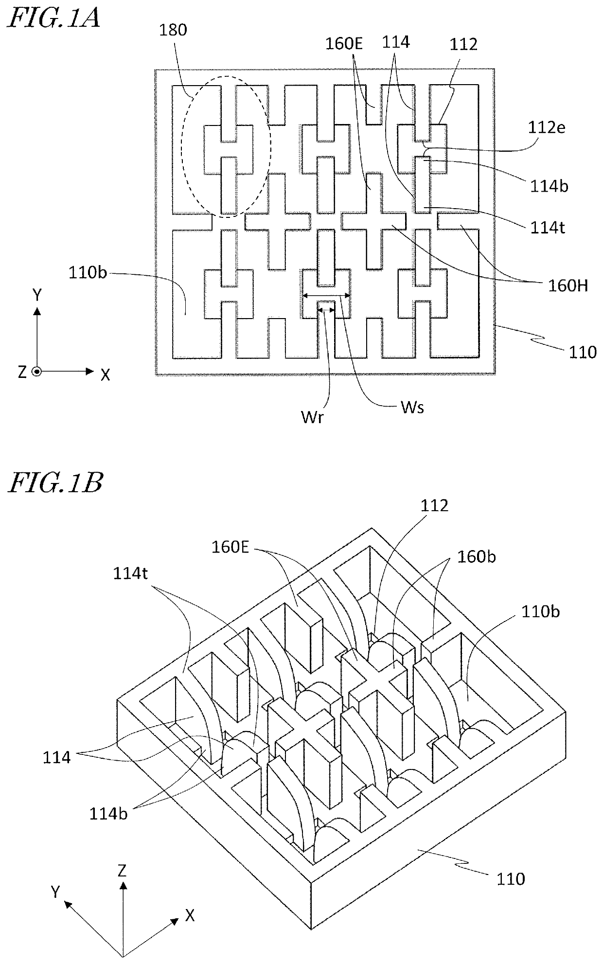
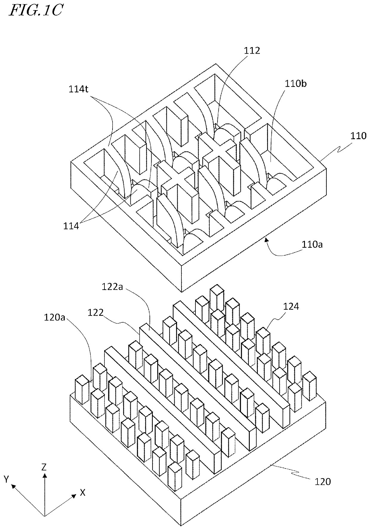
[0105]FIG. 1A is a plan view showing a ridged box horn antenna array according to Embodiment 1. FIG. 1B is a perspective view showing the ridged box horn antenna array according to Embodiment 1. FIG. 1A and FIG. 1B show XYZ coordinates representing X, Y and Z directions that are orthogonal to one another. Hereinafter, these XYZ coordinates will be used in describing any antenna array construction.
[0106]The antenna array according to the present embodiment includes an electrically conductive member 110 (hereinafter also referred to as the “base member 110”) having an electrically conductive surface 110b in which a plurality of slots 112 are open. The plurality of slots 112 extend through the conductive member 110. The plurality of slots 112 are arranged in a two-dimensional array along the X direction and along the Y direction. In the present embodiment, six slots 112 are arranged in two rows and three columns. The number and arrangement of the slots 112 may be different from those s...
embodiment 2
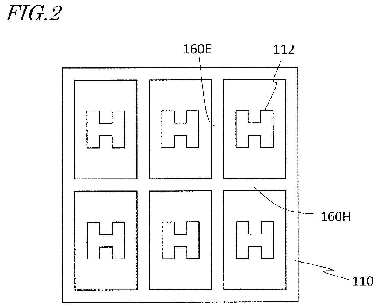
[0137]FIG. 5A is a plan view showing a ridged box horn antenna array according to Embodiment 2. Embodiment 2 lacks the inner walls 160E of Embodiment 1 that extend along the E-plane direction. The arraying interval of slots 112 along the E-plane direction (the Y direction) is 1.125λo. The arraying interval of slots 112 along the H-plane direction (the X direction) is 0.50λo. Since there exists no inner walls 160E that extend along the E-plane direction, the arraying interval of slots 112 along the H-plane direction can be further reduced relative to Embodiment 1. Except for the above aspects, the construction of the present embodiment is similar to the construction shown in FIG. 1A.
[0138]In the example of FIG. 5A, the inner wall 160H extending along the H-plane direction is partially recessed, and is not in contact with the ridge pairs 114. These recesses reach the conductive surface 110b of the base member 110. As in the example shown in FIGS. 4A and 4B, the recesses may not reach ...
embodiment 3
[0144]FIG. 8A is a plan view showing an antenna array of ridge horns according to Embodiment 3. FIG. 8B is a perspective view showing the antenna array of ridge horns according to Embodiment 3. In this antenna array, neither walls extending along the E-plane direction nor walls extending along the H-plane direction exist.
[0145]To a plate-shaped base member 110 having a plurality of slots 112, a plurality of members 113 (hereinafter referred to as “ridge members 113”) constituting a plurality of ridge pairs 114 are connected. An antenna array of such a shape will also be referred to as an “horn antenna array” in the present specification.
[0146]In the present embodiment, the arraying interval of slots 112 along the E-plane direction (the Y direction) is 1.125λo. The arraying interval of slots 112 along the H-plane direction (the X direction) is 0.50λo. As in Embodiment 2 and its variants, an antenna array with a narrow interval between slots 112 along the X direction can be realized.
[...
PUM
 Abstract
Description
Claims
Application Information
 - R&D
- Intellectual Property
- Life Sciences
- Materials
- Tech Scout
- Unparalleled Data Quality
- Higher Quality Content
- 60% Fewer Hallucinations
Browse by: Latest US Patents, China's latest patents, Technical Efficacy Thesaurus, Application Domain, Technology Topic, Popular Technical Reports.
© 2025 PatSnap. All rights reserved.Legal|Privacy policy|Modern Slavery Act Transparency Statement|Sitemap|About US| Contact US: help@patsnap.com


