Antenna array

a technology of antenna arrays and arrays, applied in the field of antenna arrays, can solve the problems of reducing the arraying interval of horns, and achieve the effect of wide band

Active Publication Date: 2019-02-21
NIDEC ELESYS +1
View PDF0 Cites 19 Cited by
  • Summary
  • Abstract
  • Description
  • Claims
  • Application Information

AI Technical Summary

Benefits of technology

[0011]According to an embodiment of the present disclosure, there is provided an antenna array in which antenna elements have a small arraying interval and which also has a wide band.

Problems solved by technology

This makes it difficult, in an array antenna in which a plurality of horn antenna elements are arranged, to reduce the arraying interval of the horns.

Method used


Image

  • Antenna array
  • Antenna array
  • Antenna array

Examples


embodiment 1

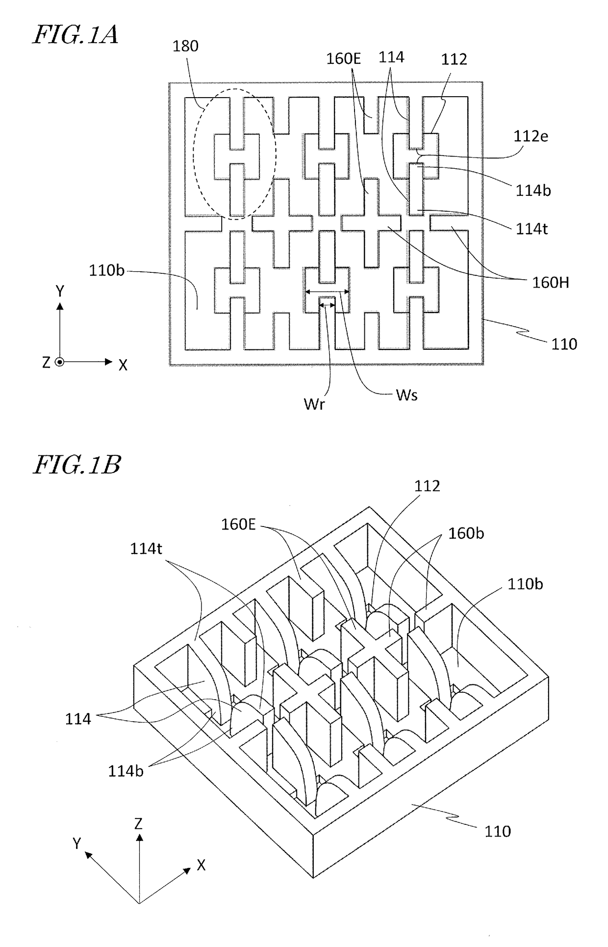
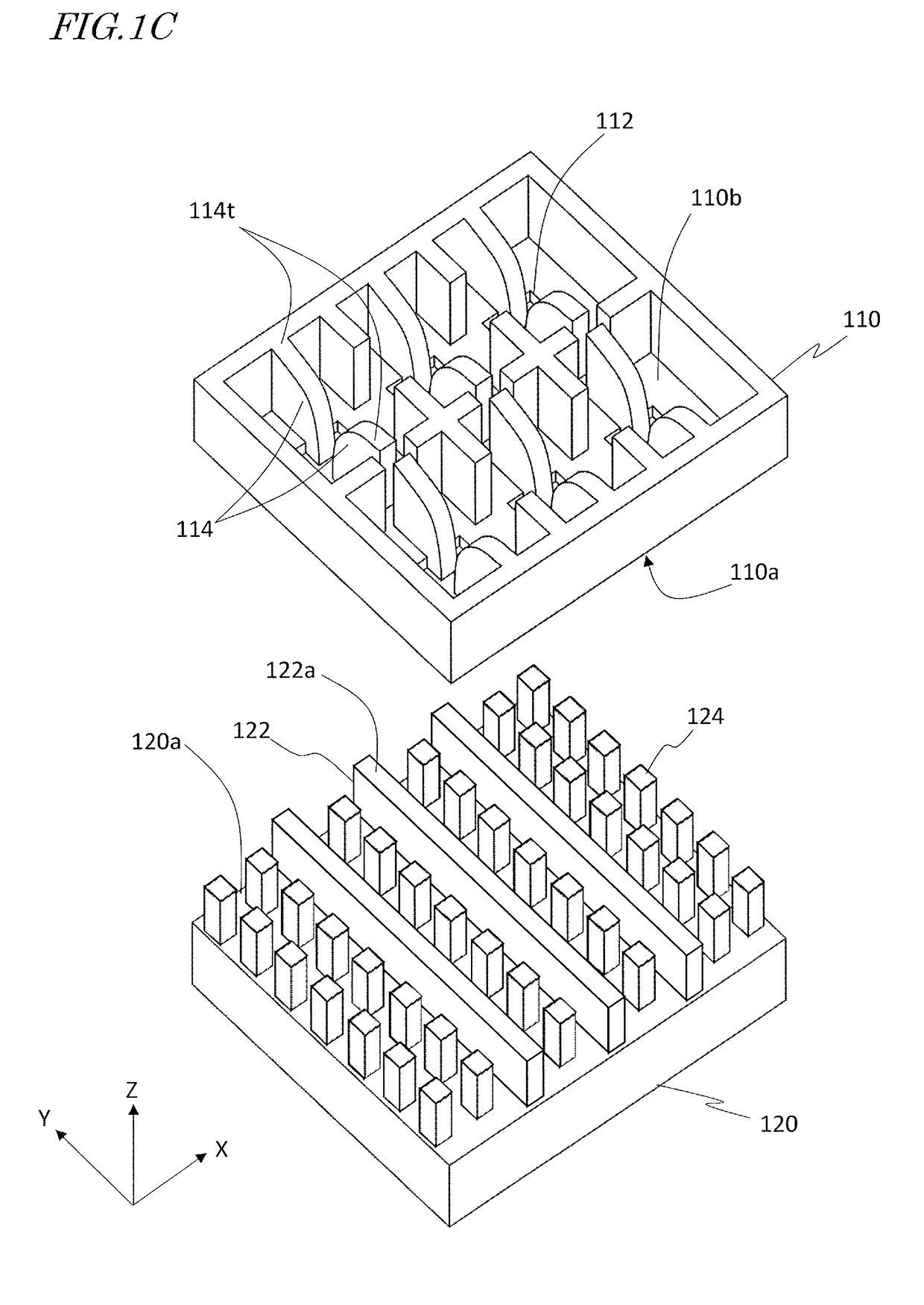
[0105]FIG. 1A is a plan view showing a ridged box horn antenna array according to Embodiment 1. FIG. 1B is a perspective view showing the ridged box horn antenna array according to Embodiment 1. FIG. 1A and FIG. 1B show XYZ coordinates representing X, Y and Z directions that are orthogonal to one another. Hereinafter, these XYZ coordinates will be used in describing any antenna array construction.

[0106]The antenna array according to the present embodiment includes an electrically conductive member 110 (hereinafter also referred to as the “base member 110”) having an electrically conductive surface 110b in which a plurality of slots 112 are open. The plurality of slots 112 extend through the conductive member 110. The plurality of slots 112 are arranged in a two-dimensional array along the X direction and along the Y direction. In the present embodiment, six slots 112 are arranged in two rows and three columns. The number and arrangement of the slots 112 may be different from those s...

embodiment 2

[0137]FIG. 5A is a plan view showing a ridged box horn antenna array according to Embodiment 2. Embodiment 2 lacks the inner walls 160E of Embodiment 1 that extend along the E-plane direction. The arraying interval of slots 112 along the E-plane direction (the Y direction) is 1.125λo. The arraying interval of slots 112 along the H-plane direction (the X direction) is 0.50λo. Since there exists no inner walls 160E that extend along the E-plane direction, the arraying interval of slots 112 along the H-plane direction can be further reduced relative to Embodiment 1. Except for the above aspects, the construction of the present embodiment is similar to the construction shown in FIG. 1A.

[0138]In the example of FIG. 5A, the inner wall 160H extending along the H-plane direction is partially recessed, and is not in contact with the ridge pairs 114. These recesses reach the conductive surface 110b of the base member 110. As in the example shown in FIGS. 4A and 4B, the recesses may not reach ...

embodiment 3

[0144]FIG. 8A is a plan view showing an antenna array of ridge horns according to Embodiment 3. FIG. 8B is a perspective view showing the antenna array of ridge horns according to Embodiment 3. In this antenna array, neither walls extending along the E-plane direction nor walls extending along the H-plane direction exist.

[0145]To a plate-shaped base member 110 having a plurality of slots 112, a plurality of members 113 (hereinafter referred to as “ridge members 113”) constituting a plurality of ridge pairs 114 are connected. An antenna array of such a shape will also be referred to as an “horn antenna array” in the present specification.

[0146]In the present embodiment, the arraying interval of slots 112 along the E-plane direction (the Y direction) is 1.125λo. The arraying interval of slots 112 along the H-plane direction (the X direction) is 0.50λo. As in Embodiment 2 and its variants, an antenna array with a narrow interval between slots 112 along the X direction can be realized.

[...


PUM


Abstract

An antenna array includes: an electrically conductive member having an electrically conductive surface in which a plurality of slots are open; a plurality of electrically-conductive ridge pairs on the electrically conductive surface, each pair protruding from edges of the central portion of a corresponding one of the plurality of slots. As viewed along a direction that the central portion of each slot extends, at least a portion of the first gap between the first ridge pair and at least a portion of the second gap between the second ridge pair overlap each other, with no other intervening electrically-conductive member therebetween; or at least a portion of the first ridge pair and at least a portion of the second ridge pair overlap each other, with no other intervening electrically-conductive member therebetween.

Description

BACKGROUND1. Technical Field[0001]The present disclosure relates to an antenna array.2. Description of the Related Art[0002]There is a known class of antenna arrays (hereinafter also referred to as “array antennas”) whose individual antenna elements are horn antennas. A horn antenna has desirable characteristics, such as capability to radiate / receive electromagnetic waves of a relatively wide frequency band. However, in order to attain such desirable characteristics, the opening of each horn antenna needs to be somewhat large. This makes it difficult, in an array antenna in which a plurality of horn antenna elements are arranged, to reduce the arraying interval of the horns. On the other hand, the performance of an array antenna generally becomes higher as the arraying interval of its antenna elements becomes smaller.[0003]Patent Document 1 discloses a slot waveguide antenna having a pair of flares functioning as a horn. A plurality of slots are arranged along the longitudinal direc...

Claims


Application Information

Patent Timeline
Patent Type & Authority Applications(United States)
IPC IPC(8): H01Q21/06H01Q21/00
CPCH01Q21/064H01Q21/0025H01Q21/005H01Q1/50H01Q13/0275H01Q21/00H01P3/123
Inventor KIRINO, HIDEKIKAMO, HIROYUKIICHINOSE, TAKESHI
Owner NIDEC ELESYS
Why Eureka
Try Eureka