Pumping facilities and control systems

a technology of control system and pumping facility, which is applied in the direction of liquid fuel engines, machines/engines, instruments, etc., can solve the problems of shutting down of the facility, and achieve the effects of saving fuel, optimizing fuel costs, and efficient operation

Active Publication Date: 2020-07-14
W S DARLEY & CO
View PDF9 Cites 116 Cited by
  • Summary
  • Abstract
  • Description
  • Claims
  • Application Information

AI Technical Summary

Benefits of technology

[0004]The present invention pertains to pumping facilities and systems which automatically adjust the speed of a pumping facility to optimize fuel costs and also automatically adjust pumping facilities to provide efficient operation. In one aspect the system is configured to automatically optimize the flow characteristics and output of the facilities of the entire system, for instance by automatically controlling the speed of an engine which powers a centrifugal pump of a facility. In one aspect the facility includes a controller configured to adjust the speed of an engine in response to an increase of fluid pressure at an intake conduit of the facility, such that the speed may be reduced to save fuel while continuing to provide a pre-set pressure output of fluid from the facility. In one aspect a user may adjust (i.e., increase the output pressure setting) a setting associated with a discharge of a first pumping facility which in turn increases the pressure of fluid at a downstream facility such that a controller automatically adjusts the downstream facility to run at a slower speed (saving fuel costs) while continuing to maintain a pre-set discharge fluid pressure. Multiple supply

Problems solved by technology

The automatic adjustments may continue repeatedly until the pump is able to maintain

Method used


Image

  • Pumping facilities and control systems
  • Pumping facilities and control systems
  • Pumping facilities and control systems

Examples


example 1

etting

[0056]

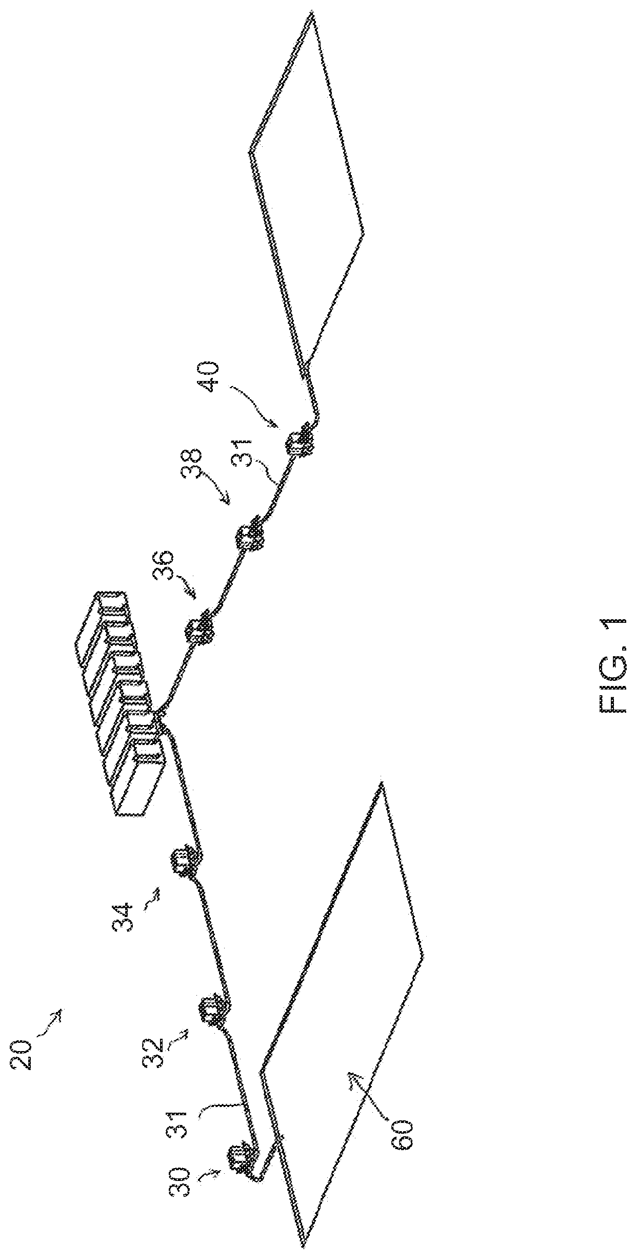
OperatorPUMPSetResultingResultingInitialReferenceDischargeInletEnginePressure Set(FIG. 1)PressurePressureSpeedBy Operator30130 PSI−12 PSI1740XRPM32150 PSI  20 PSI1740XRPM34150 PSI  30 PSI1661XRPM

Settings after Pump 30 Discharge Pressure is Changed from 130 PSI to 150 PSI:

[0057]

OperatorPUMPSetResultingResultingOperatorAutomatedReferenceDischargeInletEnginePressureSpeed(FIG. 1)PressurePressureSpeedAdjustmentAdjustment30150 PSI−12 PSI1850XRPM32150 PSI  40 PSI1503XRPM*34150 PSI  30 PSI1661RPMNOTE: Asterisk indicates an automated adjustment.

It may be appreciated that the same discharge pressure may be maintained by lowering the engine speed. The above data are approximate to + / −5 PSI and + / −20 RPM.

example 2

ettings

[0058]

OperatorInitialPUMPSetResultingResultingPressureReferenceDischargeInletEngineSet By(FIG. 1)PressurePressureSpeedOperator30130 PSI−10 PSI1740 RPMX32120 PSI  20 PSI1424 RPMX34150 PSI  30 PSI1661 RPMX

Settings after Pump 32 is Adjusted from 120 PSI to 150 PSI

[0059]

OperatorPUMPSetResultingResultingOperatorAutomatedReferenceDischargeInletEnginePressureSpeed(FIG. 1)PressurePressureSpeedAdjustmentAdjustment30130 PSI−10 PSI1740 RPM32150 PSI20 PSI1740 XRPM34150 PSI60 PSI1500XRPM*NOTE: Asterisk indicates an automated adjustment.

[0060]It may be appreciated that the above examples may also be used with the system shown in FIG. 4.

[0061]Such load leveling eases the task automatically for an operator. An operator may attend to the adjustment and monitoring remotely. An operator may log into a web based user account to control and monitor operations. The operator can send data to respective pumps or facilities 30. An operator may remotely control, for instance, the starting of a pump (d...

example 3

tor-Entered Set Up Information is Shown in the Table Below

[0067]

Initial SettingsPUMPOperator SetResultingResultingInitialOperatorReferenceDischargeInletEnginePressure SetFlow atSet Pump(FIG. 4)PressurePressureSpeedBy Operatorpump assetType41150 PSI−12 PSI1850 RPMX3200 GPMDraft38150 PSI  40 PSI1503 RPMX5300 GPMRelay36150 PSI  10 PSI1740 RPMX5300 GPMRelay34150 PSI  70 PSI1265 RPMX3200 GPMRelay32150 PSI  30 PSI1582 RPMX3200 GPMRelay30150 PSI−12 PSI1850 RPMX3200 GPMDraft43100 PSI−10 PSI1425 RPMX2100 GPMDraftNote:Pump 41 and 43 are set up in parallel

[0068]When the system is up and running the actual delivery rate at pressurized termination line 76 is 5300 GPM and the pressure is 70 PSI. The resulting delivery rate at pressurized termination line 74 is 3200 GPM and the pressure is 35 PSI.

[0069]The control system responds and makes the adjustments shown in the following table. The adjustment results in a total speed savings of 441 RPM.

[0070]

Settings After Auto AdjustmentInitialPUMPOperatin...


PUM


Abstract

A portable pump facility, pump facilities systems, and system to monitor and control a centrifugal pump include a controller configured to receive pressure and speed data from a centrifugal pump and automatically adjust the speed of an engine which drives the pump to control cavitation of the pump and to also optimize load balancing of fluid among pumping facilities. Multiple pumping facilities are provided and communicate for efficient fluid delivery, and include remote control monitoring and operation.

Description

CROSS-REFERENCE TO RELATED APPLICATIONS[0001]This application claims the benefit and priority of Provisional Patent Application Ser. No. 62 / 003,364 filed May 27, 2014, for SYSTEM FOR REMOTE MONITORING AND CONTROL OF PUMPING FACILITIES under 35 U.S.C. § 119(e), incorporated herein by reference in its entirety for continuity of disclosure.BACKGROUND OF THE INVENTION1. Field of the Invention[0002]The present invention relates to systems and pumps used for displacing liquids, and more particularly to pumps and systems that may be remotely monitored and controlled, and automatically adjusted to reduce costs and operate efficiently.2. Background Information[0003]Pumping systems that use a series of pumps to deliver liquids over a span of territory or from location-to-location are known. Pipelines for instance include pumping stations which operate to maintain a continuous flow of liquid through the pipeline or conduit. There are several challenges associated with providing an efficient de...

Claims


Application Information

Patent Timeline
IPC IPC(8): F04D15/00F04D15/02F04D29/22F04D29/42F04D13/02G01S19/14
CPCF04D13/02F04D15/0066F04D29/22F04D29/4293F04D15/0209F04D15/0088G01S19/14F04D1/06F04D13/12F04D15/029
Inventor DARLEY, KYLE M.
Owner W S DARLEY & CO
Why Eureka
Try Eureka