Projection apparatus and illumination system

a technology of projection apparatus and illumination system, which is applied in the direction of lighting and heating apparatus, semiconductor devices for light sources, instruments, etc., can solve the problems of reduced light conversion efficiency and even burning of the phosphor layer, and achieve the effect of reducing light conversion efficiency

Active Publication Date: 2020-07-14
CORETRONIC
View PDF12 Cites 0 Cited by
  • Summary
  • Abstract
  • Description
  • Claims
  • Application Information

AI Technical Summary

Benefits of technology

[0005]The disclosure provides an illumination system, which assists in solving the problems that the wavelength conversion module is burned due to excessive concentration of beam energy illuminated on the wavelength conversion module, and that the light conversion efficiency is reduced.
[0010]Based on the above, the embodiments of the disclosure have at least one of the advantages or effects below. Since the at least one light-diffusion element is inclined to the transmission path of the light beam from the light source, the light spot projected on the wavelength conversion module is expanded along a single axial direction, and thus achieving the effect of reducing the energy density of the light beam. Therefore, the illumination system of the embodiments of the disclosure can effectively solve the problems that the wavelength conversion module is burned due to excessive concentration of beam energy illuminated on the wavelength conversion module, and that the light conversion efficiency is reduced. Moreover, the projection apparatus using the illumination system of the embodiments of the disclosure can have a good performance.

Problems solved by technology

Under the illumination of a high energy light beam (such as a laser beam), the temperature of the phosphor layer increases, which causes reduction in light conversion efficiency, and the phosphor layer is even burnt.

Method used


Image

  • Projection apparatus and illumination system
  • Projection apparatus and illumination system
  • Projection apparatus and illumination system

Examples


first embodiment

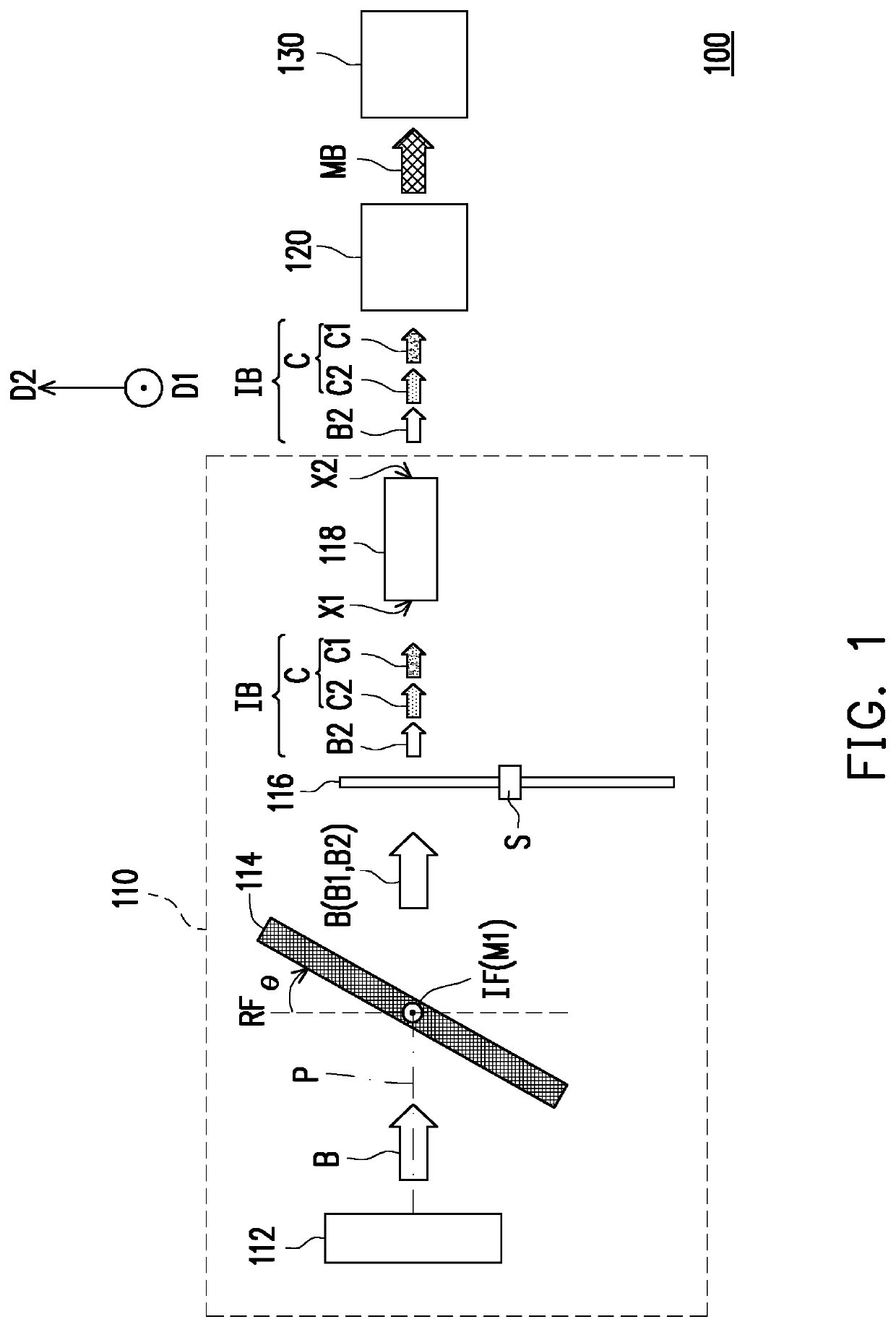
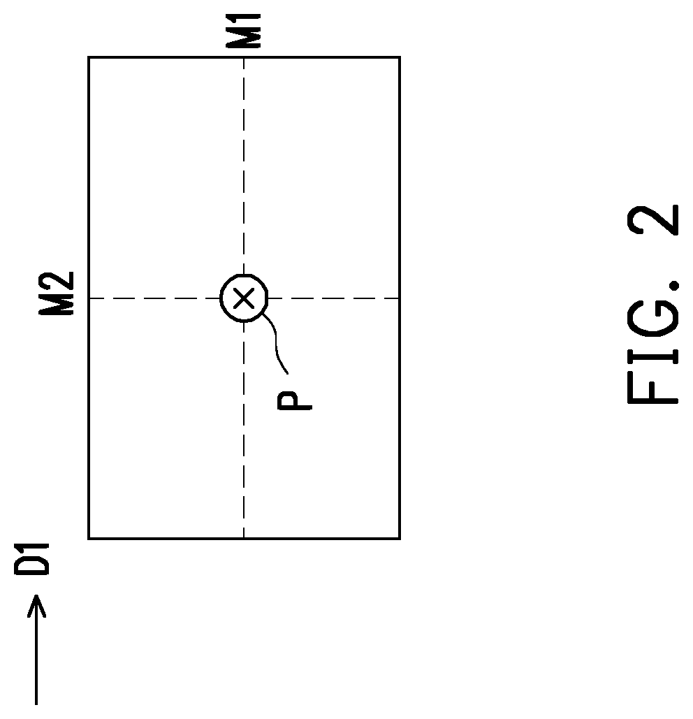
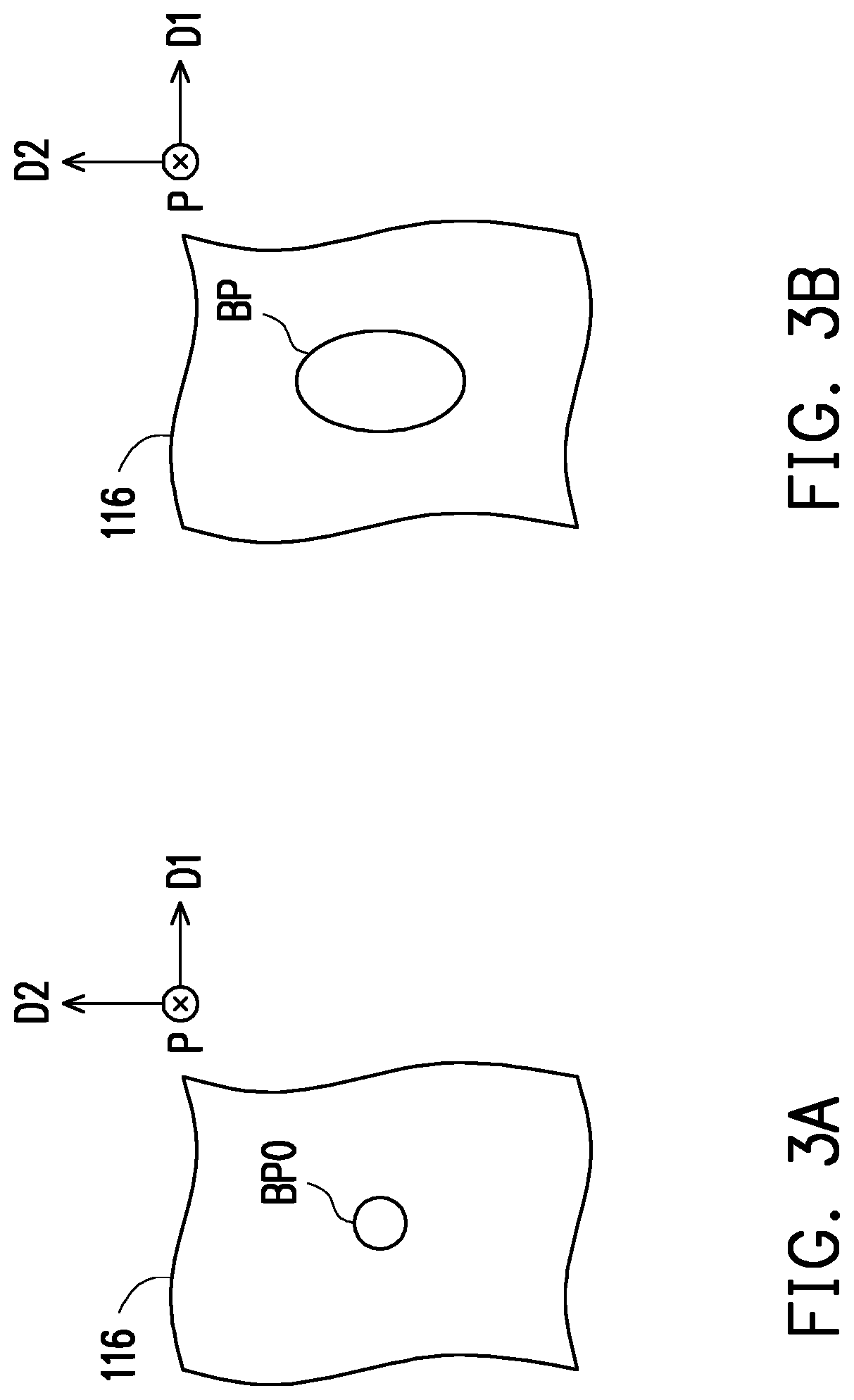
[0027]FIG. 1 is a schematic side view of a projection apparatus according to the disclosure. FIG. 2 is a front view of a light-diffusion element in FIG. 1. FIG. 3A and FIG. 3B are partial front views of a wavelength conversion module in FIG. 1, respectively, for comparing the difference of a light spot projected on the wavelength conversion module when the light-diffusion element is not inclined (FIG. 3A) and the light-diffusion element is inclined (FIG. 3B).

[0028]Referring to FIG. 1, a projection apparatus 100 of the first embodiment of the disclosure includes an illumination system 110, at least one light valve (such as a light valve 120), and a projection lens 130. In the embodiment, the projection apparatus 100 includes, for example, only one light valve (such as the light valve 120), but the disclosure is not limited thereto.

[0029]The illumination system 110 includes a light source 112, at least one light-diffusion element (such as a light-diffusion element 114), and a waveleng...

fourth embodiment

[0046]FIG. 6 is a schematic top view of a projection apparatus according to the disclosure. FIG. 7 is a front view of a light-diffusion element 114 in FIG. 6. FIG. 8A is a partial front view of a wavelength conversion module in FIG. 6 for illustrating a light spot projected on the wavelength conversion module when the light-diffusion element 114 is inclined. FIG. 8B is a front view of a light-output end of a light-homogenizing element 118 in FIG. 6 for illustrating a light spot projected on the light-output end of the light-homogenizing element 118 when the light-diffusion element 114 is inclined.

[0047]Referring to FIG. 6, a projection apparatus 400 of the fourth embodiment of the disclosure is similar to the projection apparatus 300 of FIG. 5. The main differences between the two embodiments are described as follows. In an illumination system 410 of the projection apparatus 400, the light-diffusion element 114 is disposed on a surface S of the light combiner 212 facing the light so...


PUM

PropertyMeasurementUnit
angleaaaaaaaaaa
inclined angleaaaaaaaaaa
transmissionaaaaaaaaaa

Abstract

A projection apparatus and an illumination system are provided. The illumination system includes a light source emitting a light beam, at least one light-diffusion element disposed on a transmission path of the light beam from the light source and inclined to the transmission path of the light beam from the light source, a wavelength conversion module disposed on a transmission path of the light beam from the at least one light-diffusion element. A long axis direction of a light spot projected on the wavelength conversion module is perpendicular to an extending direction of a boundary between the reference plane and the at least one light-diffusion element. The wavelength conversion module is adapted to convert a first portion of the light beam from the light-diffusion element to a converted light beam. The converted light beam and a second portion of the light beam from the light-diffusion element form a illumination light.

Description

CROSS-REFERENCE TO RELATED APPLICATION[0001]This application claims the priority benefit of China application serial no. 201810401237.9, filed on Apr. 28, 2018 and China application serial no. 201821878702.X, filed on Nov. 15, 2018. The entirety of the above-mentioned patent application is hereby incorporated by reference herein and made a part of this specification.BACKGROUND OF THE INVENTIONField of the Disclosure[0002]The disclosure relates to an optical apparatus and an illumination system, more specifically relates to a projection apparatus and an illumination system.Description of Related Art[0003]The projection apparatus generally uses the light-emitting element together with the wavelength conversion module (such as a phosphor layer) to generate a light beam for illumination. However, the phosphor layer absorbs external energy. Under the illumination of a high energy light beam (such as a laser beam), the temperature of the phosphor layer increases, which causes reduction in...

Claims


Application Information

Patent Timeline
Patent Type & Authority Patents(United States)
IPC IPC(8): G03B21/20G02B5/02G02B27/09G02B27/10G02B27/30G03B21/14
CPCG03B21/142G03B21/2006G02B5/0205G02B27/30G03B21/204G02B27/0955G02B27/1006G03B21/2013G03B21/208F21V9/20F21V9/30F21Y2115/10F21Y2115/30G03B21/16G03B21/2066G02B27/0905
Inventor CHEN, CHANG-HSUANLIAO, CHIEN-CHUNG
Owner CORETRONIC
Why Eureka
Try Eureka