Membrane element and membrane element end member used in same

a membrane element and end member technology, applied in membrane technology, membranes, ultrafiltration, etc., can solve the problem of imposing a limit on an increase in the area of the membrane, and achieve the effect of uniform wounding, sufficient adhesion strength, and uniform wounding

Active Publication Date: 2020-07-21
NITTO DENKO CORP
View PDF27 Cites 1 Cited by
  • Summary
  • Abstract
  • Description
  • Claims
  • Application Information

AI Technical Summary

Benefits of technology

[0012]Reversely, when the outside diameter of the membrane wound body is smaller relatively to the position of the circularly formed protrusions, the winding of the glass fiber roving becomes uneven (large gaps are partially generated), in particular, near tips of the protrusions. At the positions, there is caused a problem that the adhering strength of the exterior member is lowered. In any one of these cases, the circularly formed protrusions decrease the effect of heightening the adhering strength of the exterior member.
[0029]Furthermore, it is preferred that the flexible portions are arranged at 10 sites or more at substantially regular intervals. This structure makes the width of the flexible portions relatively small in the peripheral direction, so that the portions easily ensure flexibility in the radius direction. The setup of the flexible portions at 10 sites or more at substantially regular intervals makes it possible to wind the reinforcing fiber more evenly and also enhance the effect of reinforcing the adhering strength of the exterior member.

Problems solved by technology

Moreover, the outside diameter of the membrane wound body is restricted so that a limitation is imposed onto an increase of the membrane in area.
However, the latter type has a problem that at the time of the winding the glass fiber roving, the glass fiber roving is depressed down at the boundary between the membrane wound body and the end member.

Method used


Image

  • Membrane element and membrane element end member used in same
  • Membrane element and membrane element end member used in same
  • Membrane element and membrane element end member used in same

Examples


Embodiment Construction

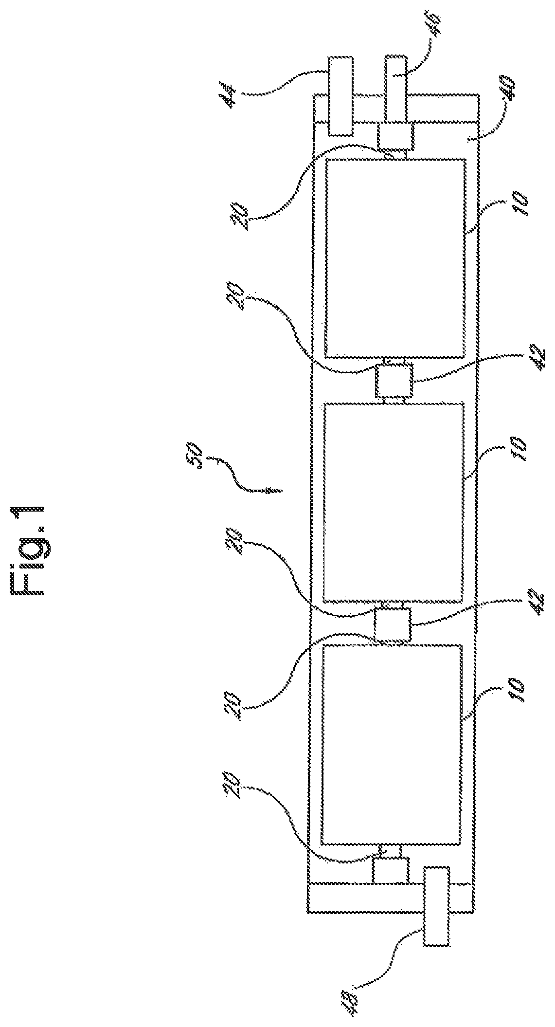
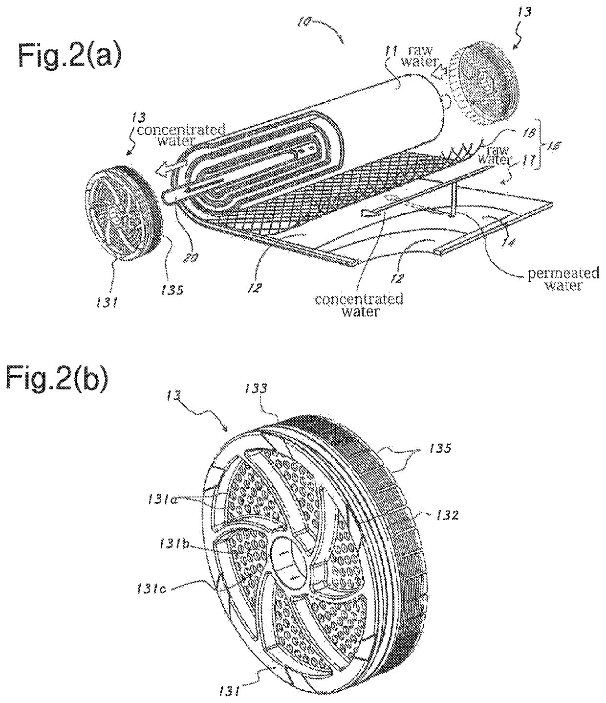
[0037]FIG. 1 is a schematic sectional view illustrating an example of a membrane filtration apparatus 50 having membrane elements 10 according to an embodiment of the present invention. FIGS. 2(a) to 2(b) are, respectively, an exploded perspective view of any one of the membrane elements 10 and a perspective view illustrating any one of its end members 13. In the illustrated example, the membrane filtration apparatus 50 is formed by arranging the membrane elements 10 straightly inside a pressure resistant vessel 40.

[0038]The pressure resistant vessel 40 is a cylindrical body made of resin or some other, and is made of, for example, an FRP (fiberglass reinforced plastic). Inside this pressure resistant vessel 40, along the axial line direction thereof, the membrane elements 10 are arranged side by side. At one out of two ends of the pressure resistant vessel 40, a raw water inflow opening 48 is made through which a raw water (raw liquid) such as waste water and seawater flows into th...


PUM

PropertyMeasurementUnit
depthaaaaaaaaaa
thicknessaaaaaaaaaa
thicknessaaaaaaaaaa

Abstract

A membrane element includes a central pipe having, in its outer periphery, holes; a membrane wound body in which a membrane member is wound on the central pipe; end members arranged, respectively, at both ends of the membrane wound body; and an exterior member fitted to at least an outer periphery of the membrane wound body. In this element, the exterior member includes a fiber reinforced resin having a reinforcing fiber wound on the outer periphery of the membrane wound body; the end members each includes flexible portions extended from a main body toward the membrane wound body; and the reinforcing fiber is wound also onto an outer periphery of the flexible portions in a state that the flexible portions are deformed toward an outer peripheral surface of the membrane wound body.

Description

TECHNICAL FIELD[0001]The present invention relates to a spiral membrane element having an exterior member including a fiber reinforced resin, and a membrane element end member used in this element.BACKGROUND ART[0002]As an example of a membrane filtration apparatus for filtrating a raw liquid through a membrane element to produce a permeated liquid, known is a membrane filtration apparatus equipped with a membrane element having a membrane wound body formed by winding a membrane member, and with a pressure-resistant vessel in which this membrane element is accommodated.[0003]A membrane wound body in the membrane filtration apparatus of this type is formed by winding a membrane member up. Thus, the membrane member may be shifted out of position into the axial line direction by pressure in the axial line direction that is received from, for example, a raw liquid flowing the pressure resistant vessel, so that the membrane wound body may be deformed into a telescope form. Against such a...

Claims


Application Information

Patent Timeline
Patent Type & Authority Patents(United States)
IPC IPC(8): B01D63/12B01D63/10B01D61/18B01D63/06
CPCB01D63/068B01D63/12B01D63/106B01D61/18B01D2313/04B01D2313/206B01D63/103B01D65/003B01D2313/041B01D2325/40B01D2313/21B01D2313/042
Inventor MATSUDA, HIDEKICHIKURA, SHINICHIUDA, YASUHIRO
Owner NITTO DENKO CORP
Why Eureka
Try Eureka