Blood pump bearing with integrated fluid diffuser/inducer system

a blood pump and diffuser technology, applied in the direction of sliding contact bearings, prosthesis, mechanical equipment, etc., can solve the problems of thrombosis and blood hemolysis in the pump, and achieve the effect of blood pump designs, and reducing the number of thrombosis

Active Publication Date: 2020-07-28
RBTS INC
View PDF20 Cites 9 Cited by
  • Summary
  • Abstract
  • Description
  • Claims
  • Application Information

AI Technical Summary

Benefits of technology

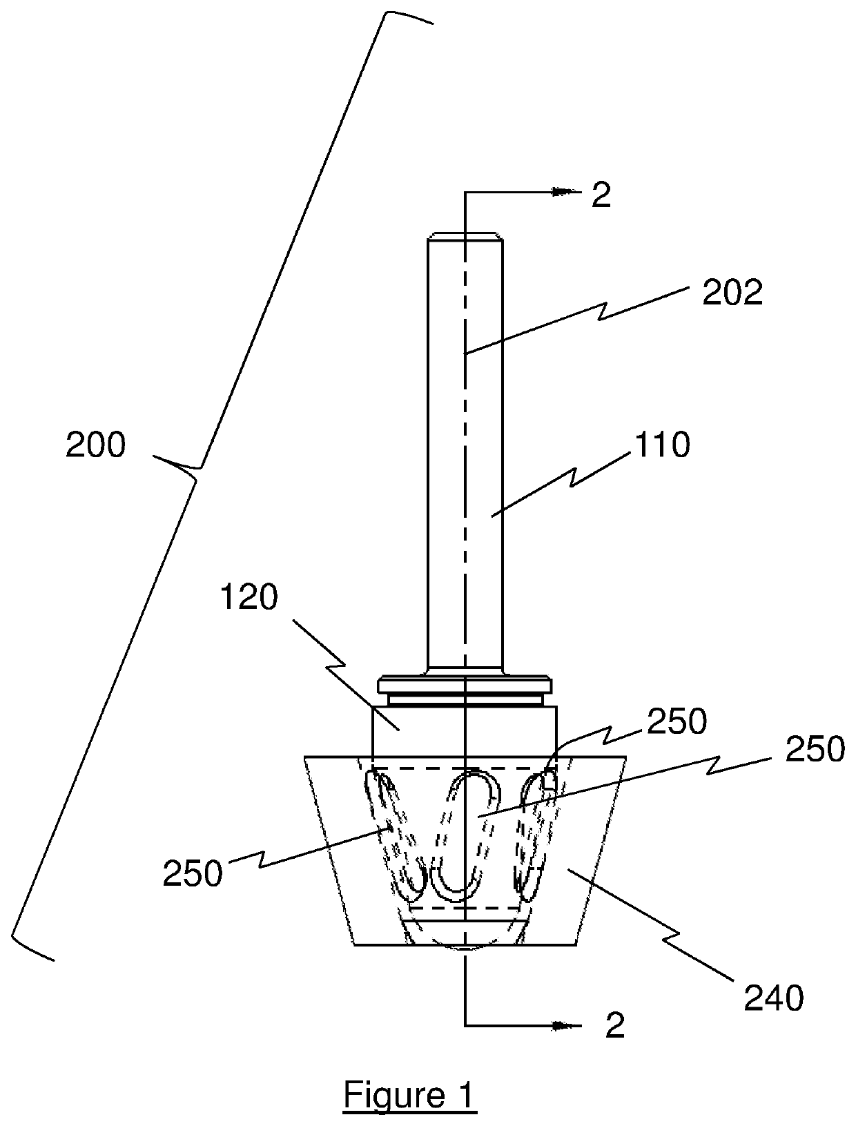
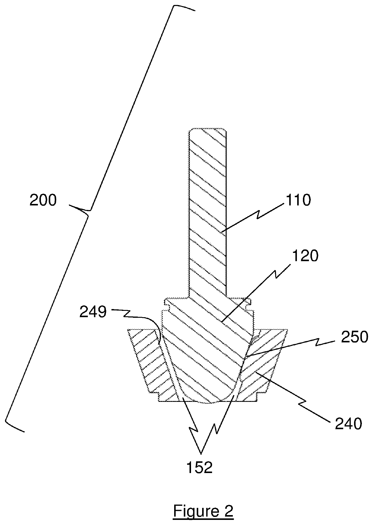
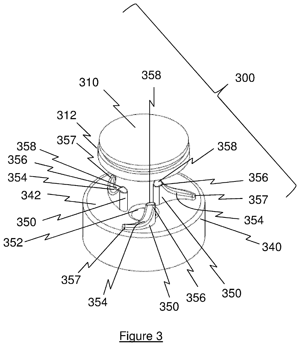
[0005]By application of novel bearing geometry with integrated vanes rotating in an open annular area design, through which blood flow continually flushes, this invention eliminates stasis within the pump bearings solving the problem of thrombus formation. A purposefully designed ultra-thin elasto-hydrodynamic lubrication layer prevents red blood cells from entering the bearing running gap between bearing sliding surfaces (i.e. “bearing” and “journal”), thereby eliminating hemolysis within the bearing system. The use of select pairs of advanced engineering materials, designed with properly sized surfaces and curvatures, and tribological pressure-velocity (PV) analysis for such materials pairs, provides a zero wear to extremely-low wear bearing system. Lastly, the inventive use of integrated bearings and vanes to guide, support and locate the rotating assembly provides for a very compact bearing and vane structure which results in more compact blood pump designs where the vanes add active pumping to the blood flow within the bearing and pump assembly, to better flush, eliminate areas of flow stasis, remove heat, and augment the primary pumping objective.

Problems solved by technology

One recurring problem with the current bearing designs is thrombus formation within the pumps, often starting in areas of blood stasis formed by the bearings and / or bearing support structure.
A second recurring problem is blood hemolysis due to excessive shear stress being applied to the red blood cells as they pass through the rotor bearing system.

Method used


Image

  • Blood pump bearing with integrated fluid diffuser/inducer system
  • Blood pump bearing with integrated fluid diffuser/inducer system
  • Blood pump bearing with integrated fluid diffuser/inducer system

Examples


Embodiment Construction

[0025]In the drawings, like numerals indicate like elements throughout. Certain terminology is used herein for convenience only and is not to be taken as a limitation on the present invention. The terminology includes the words specifically mentioned, derivatives thereof and words of similar import. The embodiments illustrated below are not intended to be exhaustive or to limit the invention to the precise form disclosed. These embodiments are chosen and described to best explain the principle of the invention and its application and practical use and to enable others skilled in the art to best utilize the invention.

[0026]Reference herein to “one embodiment” or “an embodiment” means that a particular feature, structure, or characteristic described in connection with the embodiment can be included in at least one embodiment of the invention. The appearances of the phrase “in one embodiment” in various places in the specification are not necessarily all referring to the same embodimen...


PUM


Abstract

A shallow angle rotor bearing-vane system includes a smooth angled non-rotating journal component and a mating angled bearing/vane component, incorporating a plurality of integrated bearing/vanes oriented in a generally radial direction, which provide axial and radial load carrying support between the rotating components, and pumping action to the blood. The load carrying bearing surface situated in very close running proximity to the mating bearing component to prevent entry of red blood cells between the mating bearing surfaces, thereby creating a bearing operating in an elasto-hydrodynamic regime of mixed-lubrication or boundary-lubrication.

Description

CROSS-REFERENCE TO RELATED APPLICATION[0001]The present application claims priority from U.S. Provisional Patent Application Ser. No. 62 / 676,005, filed on May 24, 2018, which is incorporated herein by reference in its entirety.BACKGROUND OF THE INVENTIONField of the Invention[0002]The present invention relates to the field of rotary pumps. In particular, this invention is drawn to bearings for various pump rotor and stator configurations.Description of the Related Art[0003]Rotary blood pumps from a variety of manufacturers have been used to treat many types of heart function degradation over the past two decades. These pumps are commonly known as mechanical circulation support systems (MCSS) including, but not limited to, the class of devices known as ventricle assist devices or VADs. Such devices can be axial, radial, or mixed flow pumps designed either for intrathoracic, intracardiac, pericardiac, intra-aortic, or intra-arterial implantation. Over time, there has been a drive towa...

Claims


Application Information

Patent Timeline
Patent Type & Authority Patents(United States)
IPC IPC(8): F16C17/10A61M1/10A61M1/12A61M60/10A61M60/216A61M60/422A61M60/812A61M60/818
CPCA61M1/1029A61M1/1013A61M2205/3334A61M1/1086A61M1/122F16C17/10F16C2316/18F16C17/105F16C33/1075F16C33/043F16C33/201F16C33/121F16C2204/42A61M60/824A61M60/422A61M60/812A61M60/216A61M60/10A61M60/818A61M60/825A61M60/416A61M60/148
Inventor OBEID, VICTORNEARY, MICHAEL DMARLINSKI, EDWARD
Owner RBTS INC
Why Eureka
Try Eureka