
Power source system

a power source and power supply technology, applied in the direction of emergency power supply arrangements, electric devices, propulsion by batteries/cells, etc., can solve problems such as time lag, and achieve the effect of reducing power consumption

Active Publication Date: 2020-07-28
TOYOTA JIDOSHA KK
View PDF27 Cites 0 Cited by
  • Summary
  • Abstract
  • Description
  • Claims
  • Application Information

AI Technical Summary

Benefits of technology

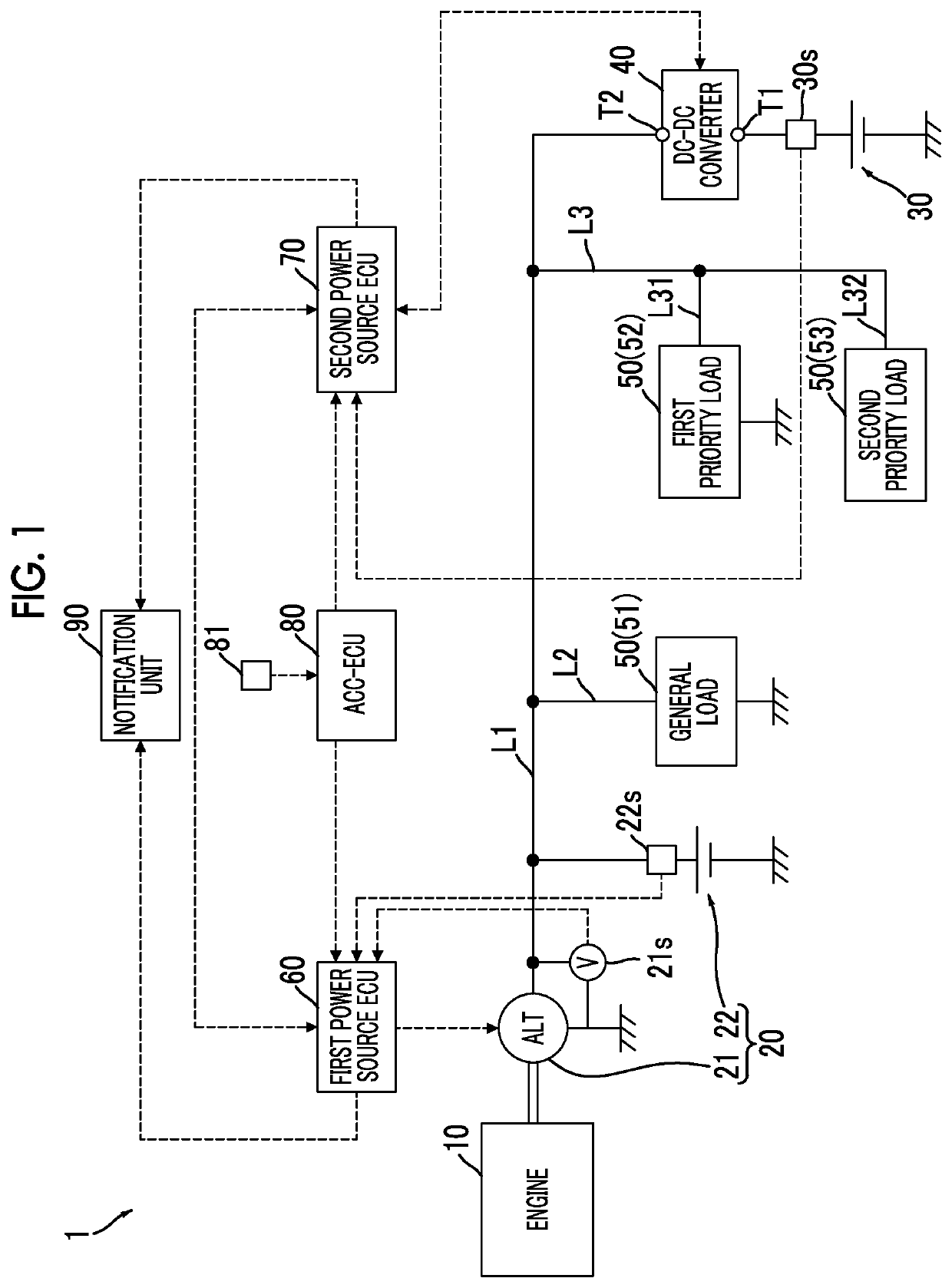
[0004]Meanwhile, there is an advance driver assistance system (ADAS) including an adaptive cruise control (ACC) system, a lane keep assist (LKA) system, an automatic brake system, and the like, or a high-grade driving assistance system such as an automatic driving system. Such a high-grade driving assistance system includes a control device (electric control unit (ECU)) performing control regarding at least one of traveling, steering, and braking of a vehicle regardless of a driving operation performed by a driver. The high-grade driving assistance system includes an electric actuator which is a control target of the control device, such as an electric hydraulic pump included in, for example, an electric power steering (EPS) motor or a brake actuator. In addition to the main power source, the sub-power source is provided (that is, double power source systems) for an electrical load such as the control device or the electric actuator implementing the high-grade driving assistance system, and, thus, even if abnormality occurs in the main power source, the electrical load can be operated with power from the sub-power source, and thus reliability can be ensured.

Problems solved by technology

Thus, if abnormality occurs in the main power source, a time lag occurs until the supply of power from the sub-power source to the electrical load is started.

Method used


Image

  • Power source system
  • Power source system
  • Power source system

Examples


second embodiment

[0142]Next, a second embodiment will be described.

[0143]A power source system 1A according to the present embodiment is different from the power source system 1 of the first embodiment in that a relay R1 and power paths L4, L41, L42 (refer to FIG. 10) are additionally provided. The power source system 1A according to the present embodiment is different from the power source system 1 of the first embodiment in that the first power source ECU 60 and the second power source ECU 70 are respectively replaced with a first power source ECU 60A and a second power source ECU 70A (refer to FIGS. 11 and 12), specifically, the control mode determination unit 601 and the DDC control unit 701 are respectively replaced with a control mode determination unit 601A and a DDC control unit 701A (refer to FIGS. 11 and 12), and a relay control unit 703A (refer to FIG. 12) is additionally provided. Hereinafter, the same constituent elements as those in the first embodiment are given the same reference num...

first embodiment

[0148]The control mode determination unit 601A and the DDC control unit 701A perform processes which are different from those in the first embodiment due to addition of the relay R1. Details thereof will be described later.

[0149]The relay control unit 703A controls an operation of the relay R1. In the normal mode, the relay control unit 703A fundamentally maintains the relay R1 in an ON state (closed state). Control states in the other control modes will be described later.

[0150]The relay control unit 703A may turn off the relay R1 according to other conditions (for example, a case where required power in the general load 51 is large, and power from the sub-battery 30 is desired to be supplied thereto as much as power supplied to the first priority load 52 and the second priority load 53) in the normal mode.

[0151]Next, with reference to FIGS. 13 to 15, control processes performed by the first power source ECU 60A and the second power source ECU 70A will be described in detail.

[0152]...

third embodiment

[0180]Next, a third embodiment will be described.

[0181]A power source system 1B according to the present embodiment is different from the power source system 1A of the second embodiment in that a relay R2 (refer to FIG. 17) is additionally provided. The power source system 1B according to the present embodiment is different from the power source system 1A of the second embodiment in that the first power source ECU 60A and the second power source ECU 70A are respectively replaced with a first power source ECU 60B and a second power source ECU 70B (refer to FIG. 17). Specifically, the power source system 1B according to the present embodiment is different from the power source system 1A of the second embodiment in that the control mode determination unit 601A, the DDC control unit 701A, and the relay control unit 703A are respectively replaced with a control mode determination unit 601B, a DDC control unit 701B, and a relay control unit 703B (none illustrated). Hereinafter, the same c...


PUM


Abstract

A power source system includes a first power source, a second power source, a Direct Current to Direct Current converter, a first load including a vehicle control device configured to perform predetermined control regarding at least one of traveling, steering, and braking of the vehicle regardless of a driving operation performed by a driver of the vehicle, and an electric actuator as a control target of the vehicle control device, and connected to the first path so as to be supplied with power from the first power source, and a power source control device configured to control an operation of the Direct Current to Direct Current converter such that power is supplied to the first path from the second power source in a case where the predetermined control is performed.

Description

INCORPORATION BY REFERENCE[0001]The disclosure of Japanese Patent Application No. 2016-113755 filed on Jun. 7, 2016 including the specification, drawings and abstract is incorporated herein by reference in its entirety.BACKGROUND1. Technical Field[0002]The present disclosure relates to a power source system.2. Description of Related Art[0003]There is an on-vehicle power source system in which a main power source, a sub-power source, and an electrical load are connected in parallel to each other, and connection and disconnection between the sub-power source and the electrical load can be performed (for example, Japanese Patent Application Publication No. 2011-246114 (JP 2011-246114 A)).SUMMARY[0004]Meanwhile, there is an advance driver assistance system (ADAS) including an adaptive cruise control (ACC) system, a lane keep assist (LKA) system, an automatic brake system, and the like, or a high-grade driving assistance system such as an automatic driving system. Such a high-grade drivi...

Claims


Application Information

Patent Timeline
Patent Type & Authority Patents(United States)
IPC IPC(8): B60L3/00B60L1/00B60R16/033B60L50/50B60L3/04
CPCB60L3/0023B60L3/0092B60L50/50B60R16/033B60L3/04B60L1/003B60L2210/10H02J9/06B60L50/60Y02T10/70
Inventor NAKAYAMA, SHUYONEYAMA, ISAOUSAMI, TOMOHIROTERADA, YASUHARU
Owner TOYOTA JIDOSHA KK
Learn More